
Welcome to GreenMore
Welcome to GreenMore
A low frequency solar inverter — also called a line frequency or transformer-based inverter — converts DC from solar panels or batteries into AC using a low frequency (50 Hz or 60 Hz) power transformer as the core voltage-conversion and isolation element. The transformer sits between the inverter bridge and the AC output, doing two jobs at once: stepping the voltage up or down, and providing galvanic isolation between the DC side and the AC side. This topology has been used in off-grid and industrial power systems for decades, and it still makes sense in a specific set of applications.
The power stage is straightforward. A DC input is switched by a full-bridge (or push-pull) inverter circuit into low frequency AC, which then passes through a power frequency transformer for voltage transformation and isolation. A filter stage smooths the output into a clean sine wave, and a control module manages voltage regulation, overload protection and, in solar systems, MPPT on the DC input side.
The transformer is the defining component. Its core is built from laminated silicon steel sheets, which keep hysteresis and eddy current losses manageable at 50 Hz / 60 Hz. Because the transformer operates at line frequency, it must be physically larger than the high frequency transformer used in a switching inverter of the same power rating. That size is the source of both the main advantage and the main trade-off of this topology.
The heavy transformer gives low frequency inverters two properties that high frequency switching inverters struggle to match at the same price point: high surge current capability and galvanic isolation by design. That makes them a natural fit for a few specific scenarios.
| Scenario | Why low frequency fits |
|---|---|
| Inductive loads with high starting current (motors, compressors, pumps, refrigerators) | Transformer-based topology handles 3× to 5× rated current surges for several cycles without tripping, which most high frequency inverters cannot sustain |
| Off-grid or weak-grid installations (rural sites, islands, telecom towers) | Galvanic isolation protects the DC side from AC-side faults and lightning-induced transients; the design tolerates dirty, unstable grids better than sensitive high frequency electronics |
| Commercial and industrial backup with mixed loads | Continuous overload capacity and simple, well-understood failure modes reduce unplanned downtime in critical loads |
| Harsh environments (high temperature, high humidity, dust) | Fewer high frequency switching stages means fewer failure points; thermal design is dominated by the transformer and large heatsinks rather than dense power electronics |
Neither topology is universally better. The right choice depends on the load profile, the installation environment and the budget.
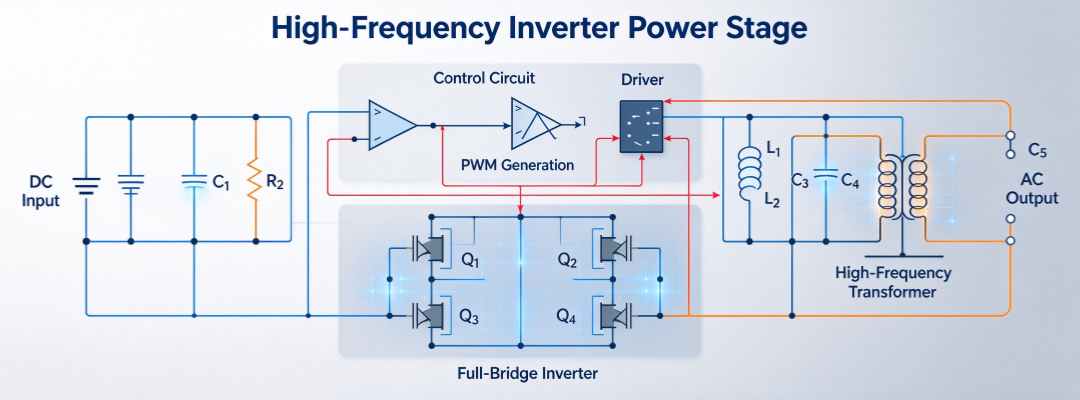
High-frequency inverter power stage circuit topology principle
| Attribute | Low frequency (transformer-based) | High frequency (switching) |
|---|---|---|
| Weight and size | Heavier and bulkier due to the line frequency transformer | Lighter and more compact; the transformer operates at tens of kHz |
| Surge / inrush handling | Strong; can sustain multi-cycle overloads | Typically limited to short, ms-scale peaks |
| Isolation | Galvanic isolation built into the main power path | Often transformerless; isolation depends on topology and design |
| Peak efficiency | Good but typically a few percentage points lower than a well-designed high frequency unit at light load | Higher peak efficiency at light and medium loads |
| Cost per kW | Copper and steel make larger units relatively expensive | Lower bill of materials for the same power rating |
| Best fit | Inductive loads, off-grid, harsh environment, critical backup | Residential rooftop solar, space-constrained installs, light loads |
A few practical items matter more than the topology label on the brochure.
If you are sizing a system around motor loads or off-grid backup, see our residential range on the home energy storage category page or the commercial range on the commercial energy storage category page. For project-specific questions, use the contact page.
No. Low frequency topology wins on surge handling and isolation; high frequency wins on weight, size and light-load efficiency. For a typical rooftop solar system with light loads, high frequency is usually the better choice. For motor-heavy or off-grid systems, low frequency is often the safer choice.
The line frequency transformer must be large enough to handle the full power at 50 Hz or 60 Hz. Transformer size scales inversely with frequency, so a 50 Hz transformer is much larger and heavier than a 20 kHz switching transformer of the same power rating.
Yes, this is one of the scenarios where the topology is a strong fit. The key is to size the inverter for the starting current of the motor, not just the running current. A 3 kW motor may need a 6 kW to 9 kW inverter for a clean start.
Yes. In a solar plus storage system, the low frequency inverter sits between the battery bank and the AC loads. It converts battery DC into clean AC and, in off-grid mode, also manages the charging path from the solar array through the charge controller.
Peter works with distributors, installers and system integrators to size residential and commercial storage around real load profiles. He focuses on LiFePO4 systems that match the inverter, grid rules and backup needs of each destination market.
Stay up to date with GreenMore. We share new BIPV solar tile releases, product and certification updates, and field notes from our projects — no fluff, just the things that matter to installers, distributors, and system integrators. If there's something you'd like to see covered, drop us a line — we read every reply.




Copyright @ 2026 GreenMore All Rights Reserved.  Network Supported
Sitemap / Blog / Xml / Privacy Policy


