Large-area BIPV curved solar tile roof array for commercial buildings by GreenMore
Home

Blog

Blog

  • Netanya Solar Roof Tile Project: 407 Tiles, One Integrated Roof
    Netanya Solar Roof Tile Project: 407 Tiles, One Integrated Roof Oct 08, 2026
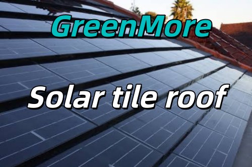
    L Luke Product Manager, GreenMore · Photovoltaic building materials Most solar roof projects start with the same question: can you generate power without turning the building into a power station? This case study walks through a real BIPV project in Netanya, Israel, where 407 curved solar tiles replaced an aging roof and started producing electricity in a single build — no racks, no drilling, no separate waterproofing layer. The numbers come from the system’s live monitoring, not lab estimates. I will share what worked, what was tricky, and why the owner chose curved tiles over flat panels even though flat panels promise more watts per unit. The existing roof before BIPV renewal. Faded and broken tiles on a four-aspect residential roof that had reached the end of its service life. Why the Owner Was Looking for an Alternative The house sits in Netanya, a coastal city north of Tel Aviv. The original roof tiles were faded and broken, and a renewal was due — a job that typically runs $20,000 to $30,000 in the region. At the same time, the owner wanted to start generating solar power. Three problems came up in early discussions: Rack-mounted panels would damage the roof. Conventional panels are drilled through the roof structure, raising leak risk and clashing with the building’s Mediterranean styling. Panels and tiles age on different clocks. Roof tiles fail long before the panels do. Renewing the roof later means removing the panels first — extra cost, extra work, and downtime. Looks and clean power rarely come together. Owners who care about curb appeal simply will not accept metal racks and exposed panels on a residential roof. The brief was clear: clean energy without giving up the roofline, the looks, or the waterproofing. That ruled out conventional panels from the start. Project Scope and Success Metrics Before any product was selected, we defined the boundaries of the job and the numbers that would count as success. Item Detail Total roof area About 140 m², with 126.4 m² of usable tiling Roof configuration Four aspects (N / E / W / S), gentle pitch around 8° Delivery model Turnkey — tiles, fittings, tier-1 inverter, battery storage, installation Contractor Single contractor, end to end. No separate purchasing for the owner. Success was defined by three measurable targets: 407 tiles — full tiling complete across all four aspects. 28,490 kWh per year — annual yield target met. Original roof untouched — complete roof renewal without demolition. All three had to be met together. Hitting the yield target with a damaged roof would not count. A perfect-looking roof with low output would not count either. The Solution: Triple-Arch Solar Tiles We selected GreenMore’s triple-arch solar tiles for this project. Three reasons drove the choice: The tile is the roof. No racks, no drilling. Tiles are laid just like ordinary roof tiles, course by course from the eaves up. Fitting tiles handle the ridge and eaves transitions. Curved profile suits Mediterranean styling. The three-arch shape reads as a traditional roof across all four aspects, rather than a grid of flat panels bolted on top. Integrated waterproofing. The solar tile itself becomes the new waterproof layer. Single-tile replacement is possible, and the ventilated rear keeps cells cool. System configuration 407 triple-arch tiles  ·  126.4 m² coverage  ·  tier-1 inverter  ·  battery storage  ·  on/off-grid ready We did consider flat tiles with optimizers. Flat tiles give more watts per unit, but the racked look and the separate waterproofing layer fell short of the brief. After evaluation, we held to the integrated curved-tile route. Looks and waterproofing were hard constraints; output was optimised within them. Construction in progress. Curved solar tiles being laid across the four-aspect roof, course by course from the eaves upward. Fixing battens and tile placement detail. The existing roof structure was left intact underneath the new solar tiles. Construction Timeline The build ran in six stages, delivered by a single crew from survey to commissioning: Stage What happened 1. Survey & design Roof measured, string layout set for four aspects 2. Materials on site Tiles, fittings, inverter, and battery delivered 3. Battens installed Fixing battens laid across the existing roof structure 4. Tiling, 4 aspects 407 tiles laid by slope, north through south 5. Flashing & trim Detail work at valleys, ridges, and junctions 6. Commissioning Inverter, battery, and grid connection tested The Hard Parts and How We Handled Them 1. Balancing output across four aspects A four-aspect roof means each face receives very different sunlight. The north face gets the least, the south face the most. If you wire them carelessly, the weakest face drags the whole string down. The fix was thoughtful string sizing — grouping tiles by aspect and wiring them so the weaker faces do not bottleneck the stronger ones. The gentle 8° pitch helps here too: at such a shallow angle, every aspect sees relatively even light throughout the day. Average daily yield settled at 74.8 kWh across all four faces. 2. Keeping the roof fully watertight No drilling, no racks. Fitting tiles handle the ridge and eaves transitions, and the solar tiles themselves become the new waterproof layer. The existing roof was left untouched underneath — no demolition, no exposure to weather during the build. The system meets EN 14782 requirements for self-supporting metal sheets used in roofing. 3. The curved-tile trade-off Flat tiles generate more watts per unit. That is a fact. But on this roof, the racked look and the separate waterproofing requirement did not meet the brief. The owner’s priorities were clear: roofline unity and waterproofing came first, output came second. Within those constraints, the curved-tile route delivered a stronger overall result. The completed BIPV roof. 407 triple-arch solar tiles covering all four aspects, with integrated waterproofing and a seamless roofline. Results: Before and After BEFORE Faded, broken tiles — $20–30k renewal due Zero self-generated solar Rack-mounted options would damage the roof AFTER 74.8 kWh average daily yield 28,490 kWh annual equivalent yield $4,826 annual bill savings Investment and payback Item Value Total investment $60,000 turnkey Nominal payback About 12 years (solar only) Actual payback About 6 years, net of the $20–30k roof renewal that would have been needed anyway The payback number changes dramatically once you count the roof renewal as a line the owner was going to pay regardless. Solar tiles replace that cost rather than adding to it. That is the real economics of a BIPV roof replacement. Live monitoring data from October 9, 2026. PV power (yellow) peaks past 11 kW at midday, battery (green) stores surplus and discharges in the evening to cover the household load (purple). What the Live Monitoring Shows These figures come from the system’s own monitoring app, recorded on a clear day in early October: Midday (12:41): 35.30 kWh generated so far that day. Battery at 98%, solar feeding 11.43 kW into the system. Power curve peak: 91.46 kWh total for the day — a clear day can top 90 kWh. Evening (20:03): 74.80 kWh total generation. Solar at zero, battery discharging at 3.61 kW to cover the 3.60 kW load. Grid draw: 7 W. Four aspects at about 8° pitch. The string sizing and the shallow angle close the gap between faces, so no single aspect becomes a bottleneck. The daily average of 74.8 kWh is what the system delivers consistently, not just on its best day. Triple-Arch Tiles vs Conventional Panels Dimension Conventional panels GreenMore triple-arch tiles Mounting Metal racks, drilled through the roof No racks — laid like ordinary tiles Roof impact Breaks the waterproof layer, leak risk The tile is the waterproof layer — full renewal Appearance Visible panels clash with the building Curved profile matches traditional tiles, seamless Upkeep Tiles and panels age apart; renewal means stripping panels Replace a single tile; ventilated rear cooling Overall payback Similar nominal payback, plus a separate roof-renewal bill About 6 years once renewal cost is counted Both options generate power. The difference is what else you get: waterproofing, a renewed roof, and a building that still looks like a house. The International Energy Agency’s Solar Energy Buildings programme (Task 66) notes that building-integrated PV is growing fastest in markets where appearance and building code compliance matter — exactly the conditions on this project. Three Things This Project Taught Us 1. Pick the strategy from the pitch On gentle multi-aspect roofs, full curved-tile coverage receives light evenly, for steadier output and higher efficiency. Pitch is the first variable to assess on projects like this. 2. Bring the renewal cost into the math Solar tiles replace a roof renewal that would have cost $20–30k. Once that line is counted, the real economics stand out. Comparing solar tiles to panels without counting the avoided renewal cost is not a fair comparison. 3. Ask first what the owner cares about most Where looks and waterproofing lead, choose curved tiles — then use turnkey delivery (materials, build, branded electrical) to lower the decision barrier. The owner should not have to coordinate three separate suppliers. One line: not just a generating roof, but a complete answer for looks, waterproofing, and returns. If your roof is due for renewal and you are considering solar, the two decisions do not have to be made separately. Request a roof assessment L Luke · Product Manager, GreenMore Luke has worked in the solar industry since 2017, focusing on BIPV product development and project delivery. He writes about real installations, real numbers, and the trade-offs that come up on actual roofs.
  • OVP, OCP, SCP, OTP: A Practical Guide to DC Power Protection
    OVP, OCP, SCP, OTP: A Practical Guide to DC Power Protection Sep 21, 2026
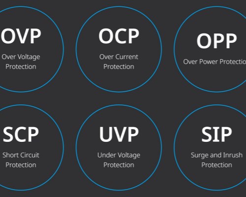
    P Peter Lu Energy Storage Product Manager, GreenMore · Energy storage systems A DC power module sitting in an energy storage cabinet has to survive events no operator plans for. A maintenance crew lands the battery leads on the wrong terminals. A summer thunderstorm couples a surge onto the DC bus. A fan bearing seizes and the heatsink starts to climb. At a remote telecom site, the feeder voltage sags every evening when the village load peaks. This is the fourth post in our series on GreenMore DC power modules. It explains what OVP, OCP, SCP and OTP actually guard against, why reverse polarity, surge and insulation monitoring belong on the same feature list, and how a wide input voltage range keeps a site running through grid and battery swings. It also gives you a checklist for verifying protection before you specify a module. Why Do DC Power Modules Need Four Separate Protections? Each protection answers a different failure mode, and none is a substitute for another. The thinking behind this layered approach matches how modern product safety standards are written. IEC 62368-1 is a hazard-based standard. It asks designers to identify electrical, thermal and fire energy sources and put safeguards between them and people or equipment. The standard replaced the older IEC 60065 and IEC 60950-1 and moved toward performance-based requirements, as TÜV Rheinland summarizes in its overview of the IEC 62368-1 transition. Its component annex covers overcurrent protective devices and thermal cut-offs, and it requires a protective device to have enough breaking capacity to interrupt the maximum fault current. Translated to the field, that framework maps to four common faults: Protection Fault Common cause Consequence Response OVP Output or bus overvoltage Regulator failure, load dump, battery disconnection under load Sensitive loads and DC-side capacitors see a voltage above rating and can fail instantly Clamp or shut down the output; restart only after voltage returns to range OCP Sustained overcurrent Overload, stalled load, partial wiring fault Semiconductors and cables overheat; accelerated wear or fire risk Current limit, then reduce or cut output if the overload persists SCP Hard short circuit Tool dropped across bus bars, insulation failure, shorted cable Near-instant destructive current; arcing and fire at the fault point Fast current cutoff; restart attempts timed to limit energy OTP Overtemperature Fan blocked, high ambient, clogged filter, prolonged overload Thermal runaway, component derating, shortened service life Throttle or shut down; auto-resume after cooling Response behavior generally falls into two families. In hiccup mode, the converter shuts off, waits, and attempts a soft restart, repeating the cycle until the fault clears. Texas Instruments notes that hiccup gives a system "a chance to recover without external intervention" while cutting power and heat during a short; see their article on hiccup and latch-off fault responses. The alternative is latch-off, which holds the converter off until the enable pin or supply is cycled, a safer choice when a central controller must decide what happens next. Exact thresholds and restart behavior vary by design, so confirm them in the product manual before commissioning. What Are Reverse Polarity, Surge Protection and Insulation Monitoring? Beyond the four lettered protections, the GreenMore module spec lists three more items worth understanding. Reverse polarity protection blocks current when the positive and negative conductors are swapped. Battery banks are the usual culprit: during commissioning or a pack replacement, a single reversed connection can drive current through electrolytic capacitors and semiconductors within seconds. A series diode or, more efficiently, a MOSFET-based power path keeps the reverse voltage from reaching the module's electronics. Surge protection deals with short, high-energy transients rather than steady overvoltage. IEC 61000-4-5 is the reference standard for surge immunity testing, covering unidirectional surges generated by switching and lightning transients and defining test levels for different installation environments. Cabinet-level surge protective devices handle the bulk of a lightning or switching event, and built-in module protection covers whatever residual transient reaches the DC input. Insulation monitoring applies to unearthed DC systems. When live conductors have no solid connection to earth, a first insulation fault causes no immediate short and no breaker trips, so it can sit undetected until a second fault on the other pole creates a phase-to-phase short. An insulation monitoring device, or IMD, continuously measures the resistance between the live conductors and earth and raises an alarm as it falls. IEC 61557-8 specifies requirements for these devices for unearthed DC IT systems up to 1,500 V, including detection of the symmetrical insulation deterioration common on the DC side. It is an early-warning function, not a shutdown by itself. OVP/OCP/SCP/OTP comprehensive protection Why Does a Wide Input Voltage Range Matter on Weak Grids? A module that only accepts a narrow voltage band will nuisance-trip in environments that are already normal for many site operators. Three scenarios come up repeatedly. First, weak and remote grids. On long feeders with high line impedance, voltage drops under evening peak load. Add a diesel generator at the end of a weak line and it gets worse: genset voltage steps and dips as large loads switch in, and may drift for seconds at a time. Every bus transfer pushes the DC link around. Second, battery voltage is not constant. A battery string starts low under heavy discharge, recovers during charging, and shifts with state of charge, temperature and age. The converter has to follow the full swing rather than dropping out mid-discharge. Third, telecom power practice already assumes this spread. ETSI EN 300 132-2 defines the normal service voltage range for a nominal −48 V supply as −40.5 V to −57.0 V, a tolerance of roughly −15.6% to +18.8% around nominal. Equipment built for a narrow band can trip inside a perfectly healthy telecom room. The GreenMore GM-LDC30 and GM-LDC60 DC power modules are designed as a wide-voltage DC power module platform. The low-voltage side operates from 200 to 900 V, and the high-voltage side from 300 to 1,000 V. That window covers battery charge and discharge swings, generator stepping and weak-feeder sags without forcing a shutdown. Zero-Intervention Reliability for Unattended Sites Protection is only half the story at a site nobody visits weekly. A module that trips and then waits for a manual reset leaves an ESS or UPS offline until the next scheduled visit, which could be weeks away at a remote telecom shelter. Zero-intervention reliability means the module handles faults inside its operating envelope and returns to service on its own when conditions normalize. Hiccup-style restart after a transient short, automatic resume after a temperature event, and continued regulation across a wide input range all serve the same goal: keep the cabinet available without a truck roll. The standby draw stays below 20 W, so idle protection and monitoring do not erode site efficiency. The same logic applies across the cabinet range. GreenMore applies the principle to its air-cooled energy storage cabinets, and it carries over to liquid-cooled and containerized deployments where site visits are even more expensive. The modules run from −30 °C to +55 °C, at altitudes up to 3,000 m, with smart air cooling that only spins fans as needed, reducing one of the common causes of OTP events. How Do You Verify Protection When Selecting a DC Module? Ask for specifics instead of accepting an acronym list. Work through these points: Confirm every protection is named in the datasheet, not just implied. OVP, OCP, SCP and OTP should each appear, along with reverse polarity, surge and insulation monitoring. Request the actual trip thresholds and tolerances. An OVP set point sitting too close to normal bus voltage causes nuisance trips; one too high leaves little margin. Ask whether each fault latches off or auto-recovers, and whether the behavior can be configured over the RS485 interface. Match that choice to who responds to alarms at the site. Check that the input range covers the real battery and grid envelope, including end-of-discharge voltage and generator conditions, not just nominal. Verify the operating temperature and altitude ratings against the installation location, and confirm cooling type and airflow clearance. Confirm insulation monitoring reports through the system controller so a first earth fault triggers a visible alarm rather than a silent log entry. The other posts cover DC module fundamentals and cabinet fit, how the conversion stage reaches 98.0% to 98.6% efficiency with low ripple, and how rack modules scale through parallel expansion. GreenMore has worked in solar and power electronics since 2017, and the GM-LDC30 and GM-LDC60 carry a three-year warranty. If you are sizing a DC module with intelligent protection for an ESS, UPS, telecom or industrial control site and want help matching protection and voltage range to your conditions, talk to our team. P Peter Lu Energy Storage Product Manager, GreenMore Peter helps integrators match DC protection to real site conditions. He reviews trip thresholds, restart behavior and the battery and grid voltage envelope before a module is specified, and works with the engineering team to confirm that insulation faults and protection events are reported through the system controller so unattended sites stay online and visible without a truck roll.
  • Modular DC Power: How Parallel Expansion Scales ESS Cabinets Without Redesign
    Modular DC Power: How Parallel Expansion Scales ESS Cabinets Without Redesign Sep 21, 2026
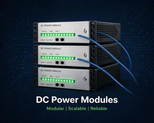
    P Peter Lu Energy Storage Product Manager, GreenMore · Energy storage systems An EPC wins a 500 kWh commercial storage project with an option to double next year. Two paths follow. Size the DC converter for day-two load and let most of it run lightly loaded for 12 months, or size it for day one and replace the unit later, which means a shutdown, re-engineering, and paying twice. A modular DC power supply offers a third path. Commission one module, then add units into the same rack as load grows. The GreenMore GM-LDC30 and GM-LDC60 support multi-module parallel expansion with active load sharing and hot-swappable replacement through the Parallel Expansion Interface. This is Part 3 of our four-part series: why parallel systems scale, how they share current, and where they fail when poorly planned. Modular vs Monolithic DC Power: Which Costs Less Over Time? A monolithic converter is one fixed block of power, sized at the factory. It is simple to specify, and at a single capacity point it can be cost-effective. Its limits show up during growth and failure. Scaling beyond its rating means a new unit. A fault takes the full block offline, and service usually requires a shutdown. Dimension Monolithic supply Modular parallel system Day-one sizing Fixed rating, all capacity paid upfront One module commissioned, racks added later Scaling Replace or add a full standalone unit Slide in more 30/60 kW modules Response to one fault Total output lost Remaining modules carry the load Maintenance Scheduled shutdown often required Hot-swap with the system online Capex profile All upfront Staged, aligned with project phases Modular hardware carries a small per-kW premium because each module has its own control and housing. It returns that premium through staged investment and service access. For EPCs and integrators building cabinets in phases, that trade usually favors modules. New to the building blocks? Start with our DC power module selection guide. How Do Parallel DC Power Modules Share Current Evenly? Paralleling converters is not just bolting them to the same bus. When two regulated sources sit in parallel, even a millivolt difference in output setpoint or unequal cable resistance pushes current toward one unit. One module overloads and overheats while the others run light. Published analyses of parallel converters show that matching terminal voltages and wiring impedances is required for an even split, and identical cable resistance is effectively impossible on site (arXiv, 2024). Three control methods handle this in practice: Droop control (passive). Each module is programmed so output voltage sags slightly as current rises. A heavily loaded unit's voltage drops, and the others pick up more current. No communication wiring is needed, so there is no signal bus to fail. The cost is a modest bus-voltage sag under load. Vicor's DCM modules, for example, use a built-in droop characteristic to share current "without additional circuitry" (Vicor applications manual). Active, average-current sharing. Modules exchange current information over a share bus, and each unit tracks the group average. Sharing accuracy is tighter, but the interconnect adds complexity and noise risk (Frontiers in Energy Research, 2021). Master-slave control. One module regulates voltage and the slaves track its current reference. It is accurate and conceptually simple, but a fixed master is a weak point. Automatic-master schemes, where leadership rotates after a fault, close that gap. GreenMore parallel DC power modules use load-sharing control to balance output current across units. Balanced current means balanced thermal stress, because the hottest module ages fastest. The conversion topology behind this, and why ripple stays low, is in Part 2 of the series. DC power supply N+1 redundancy architecture Does N+1 Redundancy Really Deliver Higher Availability? N is the number of modules needed to carry the load, and +1 is a spare unit running in parallel. ENERGY STAR's UPS specification, built on IEC 62040-3 terminology, defines N+1 as a parallel system that tolerates one unit failing while staying in normal operation; IEC 62040-3 describes parallel and standby-redundant configurations in its annexes. The numbers explain why. Following the method in the Vertiv/Liebert white paper Balancing Scalability and Reliability in the Critical Power System, a single unit's availability is: A = MTBF / (MTBF + MTTR) Illustrative values of 100,000 hours MTBF and 4 hours MTTR give A = 99.996% per unit, about 0.35 hours of expected downtime a year without redundancy. In an N+1 system the bus is available if all modules are up or exactly one is down, so for a 3+1 arrangement: A(3+1) = R⁴ + 4R³(1 − R) That yields roughly 0.3 seconds of expected downtime per year. The table compares the configurations using the same inputs. Architecture Formula (R = single-unit availability) Expected downtime per year Single unit R ≈ 0.35 h 1+1 R² + 2R(1 − R) ≈ 0.05 s 3+1 R⁴ + 4R³(1 − R) ≈ 0.30 s Worked example: a 150 kW cabinet built with four 60 kW GM-LDC60 modules in 3+1. Normally each carries 37.5 kW. When one trips, the other three carry 50 kW each, within their rating, and output continues. Two caveats keep this honest. The model assumes independent failures, but modules sharing one room, one cooling loop, or one firmware build can fail together. The same Liebert analysis also finds that beyond 3+1, added modules erode the benefit as complexity and service interventions rise; size modules so the anticipated load is carried by at most three. That principle matches Uptime Institute's Tier III, where every capacity component can be removed for planned work without impact. What Hot-Swap Maintenance Means for Downtime at 2 a.m. Picture a winter night: an alarm arrives that one DC module in an outdoor cabinet has faulted. With a monolithic supply, the sequence is a maintenance window, EMS coordination to keep the battery side stable, a service truck, and a shutdown before anyone touches hardware. With hot-swappable parallel units, a technician slides out the failed module and inserts a spare while the others keep feeding the load. The RS485 link reports slot status and recognizes the replacement automatically. Firmware updates and fan service follow the same path. For integrators deploying air-cooled ESS cabinets, this is the difference between a daytime visit and a customer-notified outage. Hot swap does not make every component redundant. The Liebert paper is explicit that a shared battery bank or a single system controller remains a single point of failure in a modular architecture. Module-level redundancy protects against module-level events. How to Plan a Scalable DC Power System with 30 kW and 60 kW Modules Practical sizing follows the load in module steps: 90 kW load: three GM-LDC30 units (N) plus one spare gives a 3+1 string; at 75 A maximum current per module, the normal split is about 56 A each at the typical battery voltage. 150 kW load: three GM-LDC60 units plus one spare, the configuration shown above. Phased build: commission a single module with the initial rack, then populate the parallel slots as later battery blocks arrive. Capacity is paid for as the project needs it. Size the rack bus, DC distribution, and switchgear for the final configuration on day one even if slots stay empty. The same logic holds for liquid-cooled cabinets and containerized projects: modules are cheap to add later; switchgear is not. Watch three traps. First, circulating current between modules with mismatched setpoints; verify setpoints before paralleling. Second, wiring asymmetry, where one module sees lower bus impedance and takes more current; use equal cable lengths and a symmetrical bus. Third, shared single points: one controller, one communications cable, or one fan group. Module redundancy is not system fault tolerance. When a module fails, the OVP, OCP, SCP, and OTP chain that isolates it is detailed in Part 4 of the series. Parallel expansion turns the DC power system from a fixed purchase into a capacity plan: single-module commissioning today, multi-unit racks next year, with load sharing and N+1 protection built in. GreenMore has worked in solar and energy storage since 2017, and our engineers bring more than 10 years of power-electronics experience to cabinet and container designs. The GM-LDC30 and GM-LDC60 carry a 3-year warranty and are ready for parallel configurations. Planning a scalable DC system for an upcoming cabinet project? Contact the GreenMore team with your load profile and expansion timeline, and we will size the string. P Peter Lu Energy Storage Product Manager, GreenMore Peter helps integrators plan parallel DC strings and phased cabinet builds. He checks the current-sharing method, redundancy level and shared single points before a configuration is locked, and works with the engineering team to confirm that bus bars, distribution and switchgear are sized for the final build from day one so capacity can be added without redesign.
  • High-Frequency DC-DC Conversion: Why Efficiency and Low Ripple Matter in ESS Cabinets
    High-Frequency DC-DC Conversion: Why Efficiency and Low Ripple Matter in ESS Cabinets Sep 21, 2026
    P Peter Lu Energy Storage Product Manager, GreenMore · Energy storage systems This is the second article in our four-part DC power guide. Part 1 covered how to choose a DC power module for an energy storage cabinet; here we look under the hood at the two numbers engineers argue about most: conversion efficiency and output ripple. Inside every modern cabinet battery converter, transistors switch thousands of times per second, chopping one DC voltage and reshaping it into another. The GreenMore GM-LDC30 and GM-LDC60 use industrial-grade high-frequency conversion to reach peak efficiencies of 98.0% and 98.6%. That sounds like a small gap. Across a 60 kW power stage running day and night, it is not. How Does High-Frequency DC-DC Conversion Work, and Why Is It Efficient? A switch-mode DC-DC converter does not burn off excess voltage the way a linear regulator does. It stores energy briefly in an inductor and transfers it in packets timed by the switch. The ratio of on-time to off-time sets the output voltage. Because the transistor is either fully on or fully off, the average dissipation in the switch stays low. Raise the switching frequency and the passive components shrink. As Texas Instruments explains, the required output inductance and capacitance are both inversely proportional to switching frequency. Double the frequency and you need roughly half the inductance, so the magnetic core gets smaller, lighter, and cheaper. That is the core reason a 60 kW converter fits in a rack-mount enclosure today while needing a cabinet of its own a generation ago. Efficiency is never free, though. At high frequency the loss budget shifts between three main components: Loss Type What It Is How It Changes Conduction loss I²R heating in switch on-resistance, inductor windings, and busbars Independent of frequency; grows with load Switching loss Energy lost while voltage and current overlap during each turn-on and turn-off Increases directly with frequency Core and drive loss Magnetic hysteresis in the core and energy needed to charge the gate each cycle Increases with frequency Resonant and phase-shifted control schemes soften the voltage-current overlap by timing the switch transition to a zero crossing, cutting the switching term. The designer's job is to pick the frequency, topology, and silicon that balance these terms. At heavy load, conduction loss dominates, so low on-resistance devices win. At light load, switching and core losses dominate, which is why the module draws less than 20 W in standby rather than idling at full magnetizing current. DC power supply low ripple characteristics What Do 98.0% and 98.6% Efficiency Actually Buy You? Efficiency converts directly into heat, which is what makes a high efficiency DC power supply module worth its price. Take each module at its rated output: Module Rated Output Peak Efficiency Power That Becomes Heat GM-LDC30 30 kW 98.0% ~600 W GM-LDC60 60 kW 98.6% ~840 W Both figures are stated at the favorable operating point; real efficiency varies with voltage ratio and load. Even so, the relationship is fixed. Every 0.1% of efficiency lost at 60 kW adds 60 W of heat, and that heat has to leave the module or it raises component temperatures. Smart air cooling handles it across the full −30 to +55 °C operating range, but hotter capacitors and semiconductors age faster. TDK notes that capacitor life is governed by thermal stress, with heat from ripple and conduction losses the deciding factor. The energy meter notices too. At a common 60 kW output, the gap between 98.0% and 98.6% efficiency is about 360 W of dissipation, or roughly 3,150 kWh per module per year if it ran continuously. Few cabinets run flat-out all year, but sites with long cycling duty see the number on their electricity bill. That is why the standby figure matters. Under 20 W keeps parasitic losses negligible when the cabinet is parked, instead of paying for a converter that wastes more in a day idle than it should. Why Low Ripple Matters for Batteries and Downstream Equipment Ripple is the periodic AC component riding on the DC output, at the switching frequency and its harmonics. It is distinct from random high-frequency noise, though the two get measured together on a scope. The output filter exists to deliver a low ripple DC output that every load on the bus can trust. Batteries are the first victim people cite. A Solis white paper reviewing 16 kW inverter testing reported that 6 A peak-to-peak ripple near 300 Hz accelerated capacity fade by up to 15% compared with smooth DC cycling, driven by localized heating and uneven lithium intercalation (Solis, The Role of Ripple Current on Lithium Battery's Lifecycle). The effect is not universally settled. Long-term academic studies reach different conclusions, and a 2022 battery-aging dataset study in Batteries found ripple effects varied with frequency and cell design. The consistent finding is that low-frequency, high-amplitude ripple does the damage; high-frequency ripple is largely filtered by the cell's double-layer capacitance. No cabinet designer should gamble a battery warranty on that distinction when the conversion stage can simply be clean. Sensitive loads share the same bus: Load How Ripple Hurts It Telecom rectifiers and radios Raises noise floor, can push transmit signal quality out of spec Sensors and analog front ends Small measurement offsets and jitter at the switching frequency Automation controllers and PLCs Logic brownouts and communication errors when dips cross thresholds DC-link capacitors Extra I²R heating shortens service life, the classic wear-out path Ripple is a steady-state power-quality problem, not a fault event. Protection such as OVP, OCP, SCP, and OTP handles abnormal conditions, which is the subject of our protection deep dive. How Should Output Ripple Be Measured? A sloppy probe setup measures the probe's own antenna loop instead of the converter. Industry practice converges on a few rules. Intel's ATX 3.0 power supply design guide defines ripple and noise over 10 Hz to 20 MHz and requires the oscilloscope bandwidth set to 20 MHz, which keeps wideband switching spikes out of the periodic ripple number. On the bench: Put the scope in AC coupling and engage the 20 MHz bandwidth limit for the ripple reading. Use a 1:1 probe or a dedicated power-rail probe for millivolt sensitivity. A 10:1 probe throws away the vertical resolution you need. Connect the probe tip directly across the output capacitor and use the short spring ground clip, not the dangling ground lead. A long ground lead is an antenna. Measure both peak-to-peak and RMS, at no load and full load. When you compare module datasheets, check the conditions first. A ripple number without a bandwidth limit and load point tells you nothing. Where the GM-LDC Modules Fit The GM-LDC30 (30 kW) and GM-LDC60 (60 kW) are bidirectional, rack-mount units. As a DC-DC converter for energy storage duty, each moves power in both directions between battery and bus. The low-voltage side operates from 200 to 900 V and the high-voltage side from 300 to 1,000 V, with maximum output current of 75 A for the 30 kW unit and 150 A for the 60 kW unit. Smart air cooling, IP20 ingress protection, RS485 communication, reverse-polarity and surge protection, insulation monitoring, and a 3-year warranty come standard, and modules support parallel operation for larger power stages. They sit inside air-cooled and liquid-cooled cabinet systems as well as utility-scale containerized ESS. When your cabinet needs more than 60 kW, our next article covers parallel expansion and current sharing. The GreenMore team has worked in solar and power electronics since 2017. If you are sizing the DC stage for a cabinet or container project and want help matching efficiency and ripple targets to your battery and load, talk to our engineering team. P Peter Lu Energy Storage Product Manager, GreenMore Peter helps integrators set realistic efficiency and ripple targets for cabinet and container projects. He reviews the operating point, thermal design and battery ripple sensitivity before a module is specified, and works with the engineering team to confirm parallel and protection configuration so the DC stage stays clean and predictable through years of cycling duty.
  • DC Power Modules for Energy Storage Cabinets: An Engineering Buyer's Guide
    DC Power Modules for Energy Storage Cabinets: An Engineering Buyer's Guide Sep 21, 2026
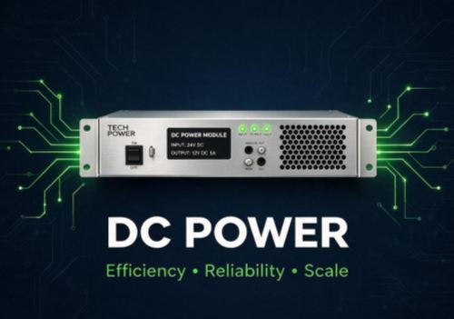
    P Peter Lu Energy Storage Product Manager, GreenMore · Energy storage systems Pick the wrong DC power module and you usually find out six months later. It shows up as a cabinet that trips on hot afternoons, a paralleled string that refuses to share current evenly, or a field trip across the country to replace a unit that never should have been sized at full nameplate. This guide is the first in a four-part series on how to specify an industrial DC power supply without learning those lessons on a live site. The GreenMore team has worked in power electronics since 2017, including the two rack-mount modules covered here: the 30 kW GM-LDC30 and the 60 kW GM-LDC60. What follows is the framework our engineers use when an EPC or integrator asks which DC power module for ESS duty fits their cabinet. What Does a DC Power Module Actually Do in a System? A DC power module sits between the battery side and the higher-voltage DC bus, converting and regulating power so each side sees a stable interface. When the battery charges, power flows one way; when it discharges into the bus, it flows the other. The front end behind it can be an AC/DC rectifier, a PCS, or another converter stage, which is why a wide tolerance for whatever that upstream device delivers matters more than a tidy single-source power architecture. The same job description comes up in four settings: Energy storage systems. Inside air-cooled and liquid-cooled cabinets and utility-scale containers, the module conditions power between LFP strings and the system bus, round the clock. Communication base stations. DC plants have run on a nominal −48 V rail for decades, with positive conductor earthed; ETSI EN 300 132-2 sets the normal service range at −40.5 to −57.0 VDC. Station-level DC conversion and backup follow different voltage tiers, and a module must match the tier it is actually wired into. Industrial automation. PLCs, drives and control boxes live in electrically noisy plants where welding machines and motor starts throw disturbances onto the rails. The IEC 61000 series defines the emissions and immunity environment such an industrial DC power supply has to survive. UPS equipment. IEC 62040-1 covers UPS safety for port voltages up to 1,000 V AC or 1,500 V DC, including systems with energy storage in the DC link. Why does component quality here get so much attention? Because power is where outages start. Uptime Institute's Annual Outage Analysis 2025 reports that power issues remain the most common cause of serious and severe data center outages, and 54% of significant outages cost over $100,000. On the storage side, U.S. Department of Energy analysis notes that recent BESS failures are now driven more by controls and power conversion systems than by cell material, with poor commissioning and miscoded converters named among the causes. The conversion stage is no place to save a few dollars. How to Choose a DC Power Module: The Specs That Matter Datasheets are long. Most selection decisions come down to eight parameters. These are the published figures for the GreenMore modules, not estimates. Parameter GM-LDC30 GM-LDC60 Why it matters Rated power 30 kW 60 kW Sets how many modules fill a cabinet Low-voltage DC side 200–900 V, max 75 A 200–900 V, max 150 A Must cover full battery voltage swing, not nominal High-voltage DC side 300–1,000 V, max 75 A 300–1,000 V, max 150 A Must match the system bus and PCS window Peak efficiency 98.0% 98.6% Drives heat, cooling load and kWh losses Cooling / ingress Smart air cooling, IP20 Smart air cooling, IP20 IP20 means indoor cabinet mounting, not outdoor exposure Operating temperature −30 to +55 °C −30 to +55 °C Check the derating curve near the top end Altitude Up to 3,000 m Up to 3,000 m Above this, dielectric and cooling assumptions change Standby consumption < 20 W < 20 W Matters when dozens of modules sit idle Three more items deserve a line each: Protection and sensing. OVP, OCP, SCP and OTP handle output overvoltage, overcurrent, short circuits and overtemperature. Reverse polarity protection, surge protection and insulation monitoring are built in as well. Communications. RS485 lets the cabinet EMS read status and issue commands. Confirm the protocol register map early, not during commissioning. Mechanical and warranty. Compact rack-mount packaging that fits standard ESS, telecom and industrial cabinets, backed by a 3-year warranty. Two sizing habits separate careful buyers from optimistic ones. First, check the real operating point: 60 kW only exists where voltage and current windows meet at the same moment, so run your actual battery voltage at end of charge and end of discharge through the module's curve. Second, respect altitude and temperature derating. A site at 3,400 m is outside the 3,000 m rating before you load it, and a cabinet in a desert yard can see internal air well above ambient if airflow is poorly planned. If you are integrating at cabinet level, compare how the module fits an air-cooled energy storage cabinet, a liquid-cooled outdoor cabinet, or a 5 MWh containerized ESS. Module heat rejection has to match the cabinet's thermal design. DC power module application scenarios Efficiency, Paralleling and Protection: Where the Other Three Guides Go Deeper Three topics get buyers into the deepest trouble, and each gets its own article in this series. High-frequency conversion is what makes 98%+ efficiency and low output ripple possible in a compact rack-mount unit, but switching topology and filter design involve real tradeoffs. We unpack them in High-Frequency DC Conversion and Low Ripple. The modular structure exists so multiple units parallel into one system and grow with the project. Current sharing, wiring and redundancy rules are not automatic, though. Modular DC Power Parallel Expansion covers how to configure it without one module carrying the whole cabinet. The intelligent protection suite, including OVP/OCP/SCP/OTP plus reverse polarity, surge and insulation monitoring, determines how a module behaves under fault rather than on a bench. DC Power Protection: OVP, OCP, SCP, OTP Explained walks through what each function should and should not be expected to do. What Selection Mistakes Do Buyers Actually Make? Four mistakes account for most of the problems we see. Buying on peak efficiency alone. A 98.6% figure measured at the sweet spot tells you little about performance at 15% load on a cold morning. Ask for the full efficiency curve and look at where your system actually runs. Ignoring the voltage windows. A battery specified at 800 V nominal still swings from roughly 600 V discharged to over 870 V at charge top, depending on chemistry and configuration. If your DC power module does not cover that full swing with usable current, part of the battery's capacity becomes unusable. Confirm both sides cover the extremes. Treating parallel capacity as plug-and-play. Dropping a second module into a rack does not guarantee equal current sharing. Bus impedance, cable length, unit tolerances and configuration all play a role, which is why the dedicated parallel-expansion article exists. Mounting an IP20 module outdoors or skipping derating. IP20 is an indoor cabinet rating. Outdoor duty needs a properly sealed cabinet, and high-temperature or high-altitude sites need deliberate derating from day one rather than a retrofit after nuisance trips. The safety standards referenced above, including IEC 62368-1 for ICT and audio-video equipment safety, are useful language to put in your specification: asking which standards a module was designed against quickly separates serious suppliers from catalogue resellers. Next Step If your cabinet voltage, battery chemistry or site conditions do not line up cleanly with the tables above, do not guess. Contact a GreenMore engineer with your one-line diagram and site conditions, and we will help you size the GM-LDC30 or GM-LDC60 for the load it will actually carry. P Peter Lu Energy Storage Product Manager, GreenMore Peter works with integrators and EPC buyers to size the GM-LDC30 and GM-LDC60 for real cabinet conditions. He checks voltage windows against the full battery swing, reviews derating for temperature and altitude, and confirms the parallel and protection configuration before an order is placed, so a module spec holds up after commissioning rather than six months into service.
  • How Solar Tiles Perform After 10,000 Days of Rain, Heat, Frost, and UV
    How Solar Tiles Perform After 10,000 Days of Rain, Heat, Frost, and UV Sep 18, 2026
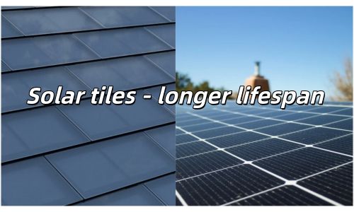
    L Luke Product Manager, GreenMore · Photovoltaic building materials These numbers come from the intersection of two engineering challenges: keeping solar cells producing electricity for three decades, and keeping a roof weathertight for just as long. When the same component has to do both, the environmental resilience requirements multiply. The Degradation Problem Every Solar Owner Faces All solar panels lose power over time. That's not a defect — it's physics. The question is how fast, and whether the rate is predictable enough to bank on for 25 or 30 years. According to a 2024 NREL meta-analysis of degradation data spanning thousands of systems, the median annual degradation rate across all crystalline silicon modules is approximately 0.5–0.7% per year. That's the industry-wide average, including budget panels and premium ones, hot climates and cool ones. But the average hides a wide spread. Premium glass-glass modules using N-type cell technology consistently show degradation rates in the 0.25–0.45% range. Field studies of double-glass modules in hot-arid climates have reported rates of 0.3–0.4% per year, compared to 0.5–0.7% for glass-backsheet designs tested under the same conditions. Here's what that gap means over the life of the system: Degradation Scenario Year 1 Loss Annual Rate Power at Year 10 Power at Year 25 Industry average (glass-backsheet) 2–3% 0.5–0.7%/yr ~93–94% ~80–84% Double-glass (glass-glass) 1–1.5% 0.3–0.4%/yr ~96–97% ~88–91% GreenMore tiled tiles (specified) ≤2% ≤0.45%/yr ~95%+ ~87%+ The 7–10% gap at year 25 isn't just an efficiency difference. On a 10 kW residential system, it represents 10,000–15,000 kWh of additional lifetime energy production — enough to power an average European household for an extra year or two over the system's life. Temperature Extremes: From Desert Noon to Arctic Dawn The −40°C to +85°C operating range covers virtually every climate where buildings exist. But operating temperature and cell temperature are different things. On a 40°C summer day with full sun, rooftop cell temperatures routinely reach 65–75°C. In desert environments like the Middle East or North Africa, peak cell temperatures can exceed 80°C. At those temperatures, every solar cell loses power. The rate of loss is defined by the temperature coefficient — typically −0.30% to −0.45%/°C for crystalline silicon. The key difference between technologies: Cell Technology Temperature Coefficient Power Loss at 65°C Polycrystalline (P-type) −0.40 to −0.45%/°C 16–18% Mono PERC (P-type) −0.34 to −0.38%/°C 13.6–15.2% BC Back-Contact (N-type) −0.29 to −0.32%/°C 11.6–12.8% GreenMore added a BC back-contact product line in 2025, using N-type cells with up to 24.1% module efficiency and a lower temperature coefficient, meaning less power loss during hot afternoons. For projects in hot climates, this difference compounds — a 4–6% annual energy advantage in places like the Middle East or Southeast Asia translates to real money saved over decades. But temperature also affects the physical materials. Repeated thermal cycling causes differential expansion in materials that expand at different rates — in a glass-backsheet module, the glass front and polymer back create shear stress on the encapsulant and cell interconnects, contributing to microcracking over time. In a glass-glass structure, both faces expand at the same rate, eliminating this thermal mismatch. It's a primary reason double-glass modules show consistently lower degradation in field studies. GreenMore solar tile weather resistance parameters UV Exposure: The Invisible Degradation Mechanism Ultraviolet radiation doesn't just affect power output — it attacks the physical materials of the module. Standard EVA encapsulant yellows under prolonged UV exposure, reducing light transmission to the cells. Polymer backsheets become brittle and develop microcracks. Anti-reflective coatings on low-quality modules deteriorate within 5–7 years in high-UV environments. A 2025 study examining crystalline silicon modules after 13 years of desert exposure (Dhahran, Saudi Arabia — peak temperatures 45°C, UV index above 11, irradiance over 1,000 W/m²) found 29.61% power loss in standard glass-backsheet modules, with encapsulant yellowing and frame corrosion as visible failure modes. The modules reached the 80% power threshold in 13 years, well short of the 25-year warranty expectation. Glass doesn't yellow. It doesn't become brittle under UV exposure. And it doesn't allow UV radiation to reach the encapsulant layer in the same way that a thin polymer backsheet does. This is why double-glass modules in the same desert conditions typically show 2× better UV resistance in accelerated aging tests. Climate-by-Climate Performance Different climates stress different aspects of a solar tile's design. Hot-arid environments test UV stability and encapsulant integrity — the 2025 desert field study showed standard modules losing nearly 30% power in just 13 years under extreme conditions. Tropical coastal zones test moisture and salt resistance, where the glass-glass structure's near-zero permeability provides a clear advantage. Cold-continental climates stress freeze-thaw cycling and snow load capacity, where symmetrical thermal expansion matters most. The IPCC Sixth Assessment Report documented that solar energy costs have fallen by up to 85% since 2010. But cost only matters if the system delivers expected energy over its lifetime. A solar roof tile that degrades 30% faster than projected in a hot climate is a bad investment regardless of how cheap it was to install. GreenMore's own specifications — targeting 0.3–0.4% annual degradation for the double-glass structure — sit at the conservative end of what premium glass-glass technology delivers. The 30-year design life accounts for the full range of environmental stressors that a roof-integrated product faces, from UV degradation to thermal cycling to moisture exposure. What This Means for Your 25-Year Energy Projection When modeling the financial return of a solar roof installation, the degradation rate assumption has a larger impact than most people realize. A 0.3%/year assumption vs. a 0.7%/year assumption produces a 10%+ difference in cumulative energy production over 25 years. For GreenMore's tiled type photovoltaic tiles, the combination of monocrystalline double-glass frameless construction and a −40°C to +85°C operating range provides a platform for stable, predictable energy production across three decades and virtually any climate zone. Projects that specifically require N-type BC back-contact cells (up to 24.1% efficiency) can select them from GreenMore's separate BC product line. The full solar tiles product range includes multiple form factors for different architectural and climatic requirements, each sharing the same double-glass structural foundation. For project-specific energy modeling and climate-based product selection, GreenMore's technical team provides support through the contact services on the company website. Solar tiles that survive 30 years of weather without needing replacement aren't a hypothetical product concept. The material science — tempered glass on both faces, stable encapsulants and monocrystalline cells with low temperature coefficients — has been validated by over a decade of field data. The question isn't whether glass-glass BIPV tiles can last. It's whether your project can afford the extra energy they'll produce along the way. L Luke Product Manager, GreenMore Luke helps distributors and EPC contractors choose the right GreenMore tile for each climate, from hot-arid UV exposure to cold-continental freeze-thaw cycles. He reviews degradation assumptions, temperature coefficients and mounting configurations before a project is quoted, so 25-year energy projections are built on realistic field data rather than best-case figures.
  • How BIPV Roof Tiles Withstand 5,400 Pa of Frontal Pressure Without Cracking
    How BIPV Roof Tiles Withstand 5,400 Pa of Frontal Pressure Without Cracking Sep 18, 2026
    L Luke Product Manager, GreenMore · Photovoltaic building materials GreenMore's tiled type photovoltaic tiles are rated for a maximum static mechanical load of 5,400 Pa on the front side and 2,400 Pa on the back side. For context, the IEC 61215-2 standard (the international qualification test for terrestrial PV modules) sets the MQT 16 static load test at a minimum of 2,400 Pa, which corresponds to a minimum design load of 1,600 Pa once the standard safety factor is applied. GreenMore's front-side rating is tested at more than twice that minimum. These numbers matter because a BIPV roof tile doesn't sit on top of a roof — it is the roof. Unlike rack-mounted panels where a separate structure absorbs wind and snow loads, the tile itself must carry the full mechanical stress and transfer it to the building structure through its mounting points. What 5,400 Pa Actually Means in Real-World Terms Pressure in Pascals can feel abstract. Here's what it translates to on the ground: Load Scenario Approximate Pressure Context Category 2 hurricane (154–177 km/h winds) 2,500–3,500 Pa Front-side load on roof surface Heavy wet snow accumulation (60 cm depth) 2,400–3,000 Pa Downward load on tilted roof IEC 61215-2 minimum test load 2,400 Pa Uniform static load qualification (MQT 16) GreenMore front-side rating 5,400 Pa More than 2× the minimum IEC test load GreenMore back-side rating 2,400 Pa Uplift resistance In high-wind regions, the ASCE 7-22 building standard (used across the United States) defines ultimate wind speeds (Vult) that vary dramatically by location. Coastal Florida faces Vult values up to 170 mph (76 m/s), while inland cities like Chicago sit around 105 mph (47 m/s). The wind pressure on a roof surface scales with the square of wind speed — which means a roof in Miami faces roughly 2.7× the wind pressure of the same roof in Chicago. The 5,400 Pa front-side rating covers most extreme wind scenarios encountered in residential and commercial rooftop installations. The 2,400 Pa back-side rating addresses negative pressure (uplift) during severe storms, where wind flowing over the roof ridge creates suction forces that try to pull the covering off the deck. Mechanical load parameters of solar tiles and schematic diagram of double-glass structure The Double-Glass Advantage for Structural Rigidity Conventional solar modules use an aluminum frame that provides structural rigidity around the perimeter. Remove the frame — as in GreenMore's frameless design — and the glass itself has to do all the work. This sounds like a liability. It's actually an advantage, once you understand the mechanics. A framed module distributes load to its four edges, where the frame transfers stress to the mounting clamps. If the frame deforms — from corrosion, thermal expansion mismatch, or impact damage — the load distribution changes and cells become vulnerable to microcracking. The frame becomes a single point of failure. A double-glass frameless tile spreads the load across the entire surface area. The symmetrical glass-glass sandwich creates a monolithic structural panel that resists bending in both directions. Under frontal load (wind pushing down, snow pressing from above), the two glass layers share the stress through the encapsulant bonding layer. Under back-side load (wind uplift suction), the same monolithic structure resists deflection uniformly. The IEC 61215-2:2021 standard's mechanical load test (MQT 16) applies uniform static pressure to the module surface for one hour. The 2021 edition also added a cyclic dynamic mechanical load test (MQT 20) that subjects modules to 1,000 cycles of positive and negative pressure — simulating the repeated gusting and lulling of real wind events. GreenMore's tiles are designed to pass both test protocols at their rated load levels. Snow Load: The Non-Uniform Problem Snow doesn't pile up evenly on a roof. In real-world conditions, snow slides down the panel surface and accumulates at the lower edge, creating a non-uniform load that puts concentrated stress on the bottom portion of the module. This is a well-documented failure mode in mountain installations. In 2020, the IEC published IEC 62938, a dedicated standard for testing PV module resistance to non-uniform snow loads. The standard simulates the real failure type: modules bending and cracking at the lower edge of sloped installations where snow accumulates unevenly. GreenMore's 5,400 Pa front-side rating addresses this scenario. The large tile format (1,378 mm × 564.8 mm) means fewer horizontal joints where snow can dam up, and the double-glass structure distributes concentrated edge loads across the full panel area rather than letting them concentrate at a single frame corner. For regions with heavy snowfall — Northern Europe, Canada, the northeastern United States, and high-altitude zones in Asia — the non-uniform snow load rating is often the governing design constraint, not wind speed. GreenMore solar tiles for cold, high-snow-loaded log cabin applications Impact Resistance: Hail, Debris, and Foot Traffic Mechanical load testing typically focuses on static pressure. But roofs also face impact events — hail, falling branches, construction debris, and occasionally maintenance foot traffic. The double-glass tempered structure provides inherent impact resistance. Tempered glass is 4–5 times stronger than annealed glass of the same thickness. When it does break (under extreme impact beyond design limits), it fractures into small, relatively blunt pieces rather than sharp shards — reducing injury risk. For BIPV tiles specifically, the impact resistance matters in another way. Because the tile is the roof covering, any impact damage that compromises the glass surface also compromises the waterproofing layer. This is different from a rack-mounted panel, where a cracked front glass surface affects power output but doesn't let water into the building. The double-glass design — with cells protected on both faces — provides a more robust impact buffer than a single-glass module with a soft polymer back. The 17.2 mm total thickness — two layers of tempered glass plus encapsulant and cells — provides the structural depth needed to achieve these load ratings without an aluminum frame. Designing for Extreme Weather Regions The mechanical load rating is just one input to the system design. Installers working in high-wind or high-snow regions need to consider the full load path — from the tile surface through the mounting system to the roof structure and finally to the building frame. GreenMore's hook-and-screw mounting system transfers loads from each tile through mechanical fasteners directly into the roof purlins or decking. The large tile format means each mounting point carries load from a larger area, but the total number of mounting points is lower than with smaller-format tiles. For engineering verification, GreenMore provides structural calculations and load tables to support permitting in different climate zones. For specific project inquiries — including load calculations for high-wind coastal sites or heavy-snow mountain installations — GreenMore's engineering team provides technical support through the contact page. The 5,400 Pa / 2,400 Pa mechanical load rating puts GreenMore's tiled type photovoltaic tiles well above the IEC 61215 qualification baseline. The double-glass frameless structure distributes stress uniformly, eliminates frame-related failure points, and provides the structural rigidity needed for a tile that serves as both the weather barrier and the power generator. For buildings in regions where extreme weather is not a theoretical risk but an annual reality, that structural margin is what keeps the roof intact and the power on. L Luke Product Manager, GreenMore Luke works with distributors, installers and EPC contractors to match GreenMore photovoltaic tiles with the wind, snow and seismic requirements of each market. Before a project is quoted, he reviews the load path, mounting layout and structural calculations so the roof performs as designed from day one. Send him your site's climate zone and roof structure for a load assessment.
  • What Class C Fire Rating Means for Your Solar Roof Tiles
    What Class C Fire Rating Means for Your Solar Roof Tiles Sep 16, 2026
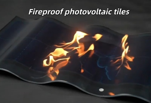
    L Luke Product Manager, GreenMore · Photovoltaic building materials GreenMore's tiled type photovoltaic tiles carry a Class C fire rating, tested in accordance with UL 790 (standard for fire tests of roof coverings) and classified under EN 13501-5 (European fire classification for external roof exposure). The Class C rating means the tile assembly has passed tests for light fire exposure — it resists flame spread across the roof surface, prevents fire penetration through the roof deck, and does not produce flying brands that could carry fire to adjacent structures. For building owners, architects, and code officials, this rating is more than a specification line item. It's the difference between a solar roof that meets building code requirements and one that creates liability exposure. GreenMore Solar Tiles Class A/B/C Fire Rating Specifications Fire Classification Levels: Where Class C Fits Roof fire ratings follow a tiered system. Under UL 790, the three classes are defined by the severity of fire exposure the roof assembly can withstand: Class Test Severity Typical Application Class A Severe fire exposure High wildfire risk zones, steep-slope commercial roofs Class B Moderate fire exposure General commercial and multi-family construction Class C Light fire exposure Residential roofing, low-to-moderate risk areas Each class requires the roof assembly to pass three evaluations: Spread of flame — how far flames travel across the surface. Burning brand resistance — whether the roof prevents ignition from burning embers. Intermittent flame — resistance to repeated flame exposure. Class C doesn't mean "low quality." It means the product has been tested and verified to perform under light external fire exposure conditions. Most residential building codes in Europe and North America require at minimum a Class C or equivalent rating for roof coverings, and many jurisdictions accept Class C for single-family homes and low-rise commercial buildings. Why Solar Roof Tiles Need Fire Certification Specifically Rooftop solar panels mounted above an existing roof inherit the fire rating of the roof assembly below them. BIPV tiles are different — they are the roof covering. This dual role as both photovoltaic generator and building envelope component means the tiles themselves must carry an independent fire classification. According to UL's BIPV testing program, BIPV roofing systems are evaluated against UL 7103, which consolidates electrical safety, fire performance, wind resistance, weather protection, and impact resistance into a single certification framework. The 2021 International Building Code (IBC) and International Residential Code (IRC) editions require BIPV roofing systems to be listed and labelled to UL 7103. In the European framework, EN 13501-5 classifies roof coverings based on external fire exposure tests defined in CEN/TS 1187. The standard uses four test methods (T1–T4), each simulating different hazard scenarios involving burning brands, wind, and radiant heat. For BIPV tiles installed as roof coverings, this classification is essential for obtaining building permits across EU member states. How Double-Glass Frameless Construction Achieves Class C The fire performance of a roof tile comes down to what it's made of and how it's put together. GreenMore's tiled type photovoltaic tiles use two layers of tempered glass — front and back — with solar cells encapsulated between them. No polymer backsheet, no aluminium frame. Glass is non-combustible. It does not ignite, does not contribute fuel to a fire, and does not produce flaming droplets. This is fundamentally different from polymer-backsheet modules, where the rear surface contains EVA, Tedlar, or other organic materials that can burn or melt under direct flame exposure. The frameless design eliminates another potential fire pathway. Aluminium frames, while not combustible themselves, create gaps between the module edge and the roof surface where embers can lodge and smoulder. A flush-mounted, frameless glass tile presents a continuous, non-combustible surface with no gaps for ember accumulation. Fireproof principle and system safety of double-glass solar roof tiles What This Means for Building Compliance Fire safety requirements for roof coverings vary by jurisdiction, but the underlying principle is consistent: the roof assembly must resist external fire spread. Here's how the Class C rating maps to common compliance scenarios: Jurisdiction Standard Requirement GreenMore Compliance European Union EN 13501-5 Roof covering fire classification required Class C (T1–T4 applicable) United States UL 790 / IBC §1505 PV panels must match roof fire classification Class C rated United Kingdom BS EN 13501-5 B_Roof(t4) typically required for high-risk areas Class C for residential/low-risk For residential roofing projects in most markets, Class C satisfies the minimum code requirement. Projects in high wildfire risk zones (such as California's WUI zones or Australian bushfire-prone areas) may require Class A — a different product category altogether. The fire rating also affects insurance. Many property insurance policies reference roof covering fire classifications when determining premiums. A certified Class C rated BIPV roof demonstrates compliance and may help avoid premium surcharges that uninspected or uncertified solar roofing installations can trigger. The Statistics Behind Roof Fire Risk The urgency of roof fire classification becomes clear when you look at the numbers. According to the National Fire Protection Association (NFPA), structure fires in the United States caused an estimated $15.3 billion in direct property damage in 2024. Nonresidential building fires alone accounted for approximately $3.16 billion in property loss in 2023, per the U.S. Fire Administration. Roof-related fires — whether originating from external embers, electrical faults, or construction activities — represent a significant portion of these losses. The NFPA reports that where sprinklers are present, fire stays confined to the room of origin 94% of the time, compared with just 70% without sprinklers. For roofs without suppression systems, the fire rating of the roof covering itself becomes the primary defence against external fire spread. Fire Safety as Part of the Full Certification Package GreenMore's approach to fire safety sits within a broader certification framework. The company's tiled type products carry EN 14782 (profiled sheeting for roofing), EN 1090-1 (structural steel/aluminium components), ISO 9001 (quality management), ISO 14001 (environmental management), and CE marking. The Class C fire rating is one component of a comprehensive compliance package that addresses structural integrity, environmental performance, and manufacturing quality. For contractors and building owners navigating the permitting process, having all certifications in order from the start avoids delays and keeps inspections on track. GreenMore has been manufacturing BIPV products since 2017, building a portfolio of 20+ patents and production capacity exceeding 1 MW to support projects of varying scale. Class C fire rating isn't the highest possible classification — but for the majority of residential and commercial roofing applications, it's the right one. It confirms that the double-glass frameless structure performs as a non-combustible roof covering under standardised test conditions, meeting the regulatory requirements that building inspectors and insurance assessors need to see. Work With GreenMore GreenMore is a photovoltaic tile manufacturer. Our three-curve solar tiles, photovoltaic bricks, and photovoltaic curtain walls are produced in-house, in CIGS thin-film and back-contact technologies, with the inverter and battery supplied as supporting components of the complete system. If you have questions about fire certification or need compliance documentation for your project, reach us through our contact page or email export@gmsolarkit.com. L Luke · Product Manager, GreenMore Luke manages GreenMore's photovoltaic building-material range, from the CIGS thin-film triple-arch tile to the newer back-contact line. In the solar industry since 2017, he focuses on designs that are genuinely buildable, with honest specs and warranty terms that match the products actually shipped.

  • Why Double-Glass Frameless Solar Tiles Outlast Traditional Modules by a Decade
    Why Double-Glass Frameless Solar Tiles Outlast Traditional Modules by a Decade Sep 10, 2026
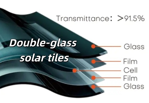
    L Luke Product Manager, GreenMore · Photovoltaic building materials GreenMore's double-glass frameless photovoltaic tiles use two layers of tempered glass encapsulating solar cells in a frameless structure, delivering a 25-year power warranty with annual degradation as low as 0.3–0.4%. Each tile measures 720 × 500 mm and installs via a hook-and-lap system that integrates directly with the roof — no separate racking step required. That's the short version. Here's why the engineering matters. The Backsheet Problem Nobody Talks About Most conventional solar modules use a glass front and a polymer backsheet — typically EVA or Tedlar. It's a design that works well for ground-mounted utility projects, where you can swap out a degraded panel without much fuss. But a roof-integrated BIPV tile is different. It is the roof. Replacing one means disturbing the waterproofing layer, the flashing, and potentially the surrounding tiles. Polymer backsheets allow water vapour permeation at rates of 1–4 g/m²/day, depending on material quality and ambient temperature. Over 15 or 20 years, that slow moisture ingress triggers the three most common field failure modes: Potential Induced Degradation (PID), encapsulant delamination, and corrosion of cell interconnects. Glass is essentially impermeable. The water vapour transmission rate through a glass-glass module is 100 to 1,000 times lower than through a polymer backsheet. This single material swap eliminates the primary degradation pathway that shortens module life in real-world conditions. According to a study published in the Oxford Academic Clean Energy journal, double-glass bifacial modules in hot-arid climates maintained a performance ratio of 91%, compared with 81% for single-glass polycrystalline panels under identical conditions. The degradation gap — 0.3–0.4% per year for glass-glass versus 0.5–0.7% for glass-backsheet — compounds into a 5–8% difference in cumulative energy production over 25 years. What 25 Years Actually Looks Like Here is a side-by-side comparison of expected power retention for the two architectures: Parameter Double-Glass (Glass-Glass) Standard (Glass-Backsheet) Year 1 degradation (LID) 1–1.5% 2–3% Annual degradation (Year 2+) 0.3–0.4%/year 0.5–0.7%/year Power retention at Year 25 88–91% 80–84% Expected physical lifespan 25–30+ years 20–25 years Product warranty 10 years (tile) / 25-year linear power 12–15 years Moisture barrier Near-zero permeability 1–4 g/m²/day GreenMore's tiled type photovoltaic tiles are engineered with this long-term performance in mind. The double-glass frameless design means there is no aluminium frame to corrode and no polymer layer to yellow or crack. Power output is guaranteed to remain above 80% at the 25-year mark, under the 25-year linear power warranty. Comparison of technical parameters between double-glass and single-glass solar tile structures Large-Format Tiles: Fewer Pieces, Fewer Failure Points A standard concrete roof tile measures roughly 300 mm × 300 mm. GreenMore's tiles at 720 × 500 mm cover more than four times that area per unit. The practical effect goes beyond faster installation. Fewer tiles means fewer joints, fewer waterproofing interfaces, and fewer electrical connections across the same roof area. Each joint is a potential water ingress point and a potential weak link in the electrical string. By reducing the total count, the system improves both structural reliability and electrical continuity. The hook-and-lap mounting system is designed so that each tile locks into place mechanically, then secures at the overlap. On a typical residential roof, this approach reduces installation time compared to smaller-format BIPV tiles or traditional rack-and-panel systems that require separate roofing and solar steps. Real-life example of a pitched roof photovoltaic system with skylights Self-Cleaning Performance in the Field The tempered glass surface on both sides of the tile provides more than just mechanical protection. Glass maintains optical clarity over decades without yellowing, unlike polymer surfaces that degrade under UV exposure. The smooth glass surface also allows rain to wash away dust, pollen, and particulate matter with minimal residue buildup. For residential installations at typical roof pitches (15°–35°), this self-cleaning effect keeps soiling losses low — usually under 2–3% annually in most climates. Agricultural or coastal sites may benefit from a semi-annual rinse, but the glass surface does not accumulate the stubborn mineral deposits that etch into degraded polymer coatings. Two Technology Lines for Different Project Needs GreenMore has been working in photovoltaics since 2017, bringing years of experience to the BIPV roofing market. The company operates two technology lines for its tiled products: Thin-film (CIGS, since 2019): Approximately 100–105 W/㎡ output, well-suited for projects where aesthetics and uniform appearance take priority. BC back-contact (added 2025): Up to 24.1% module efficiency, maximising energy output per square metre of roof area. Both technology lines share the same double-glass frameless structure. The choice between them depends on project priorities — roof orientation, available area, local electricity costs, and energy targets. For projects with specific dimensional or performance requirements, GreenMore offers customisation services to tailor tile specifications to the building's design and the owner's energy goals. The Bottom Line on Durability A solar roof tile that needs replacing at year 15 is a roofing problem, not just a solar problem. The double-glass frameless design eliminates the primary failure mechanisms that plague traditional backsheet modules — moisture ingress, UV degradation, and thermal cycling stress on asymmetric materials. Combined with the large-format installation approach and the mechanical stability of tempered glass on both faces, the result is a roofing system that is built to last as long as the building it covers. GreenMore's tiled type photovoltaic tiles are certified to EN 14782 and carry CE marking. For specifiers and contractors evaluating long-term roofing and energy solutions, the full solar tiles product range demonstrates how double-glass construction is applied across the product line, backed by a decade of field deployment experience. Work With GreenMore GreenMore is a photovoltaic tile manufacturer. Our three-curve solar tiles, photovoltaic bricks, and photovoltaic curtain walls are produced in-house, in CIGS thin-film and back-contact technologies, with the inverter and battery supplied as supporting components of the complete system. If you are planning a BIPV project or need a reliable manufacturing partner, you can reach us through our contact page or email export@gmsolarkit.com. L Luke · Product Manager, GreenMore Luke manages GreenMore's photovoltaic building-material range, from the CIGS thin-film triple-arch tile to the newer back-contact line. In the solar industry since 2017, he focuses on designs that are genuinely buildable, with honest specs and warranty terms that match the products actually shipped.
  • Full-Chain Customization for Solar Tiles & Energy Storage: The Complete B2B Guide
    Full-Chain Customization for Solar Tiles & Energy Storage: The Complete B2B Guide Sep 17, 2026
    L Luke Product Manager, GreenMore · Photovoltaic building materials In 2025, global solar photovoltaic installations reached a record 510.3 GW — nearly 75% of all new renewable capacity added worldwide (IRENA). Within this surge, the building-integrated photovoltaics (BIPV) segment is expanding rapidly: the global BIPV market was valued at approximately $24.8 billion in 2025 and is projected to reach $59.8 billion by 2034, growing at a CAGR of 10.4% (Straits Research). Rooftop applications alone account for over 66% of market share. This is not incremental growth. It is a structural shift in how buildings generate, store, and manage energy — and it is creating significant demand for customized solar products. For distributors, EPC companies, and system integrators, the opportunity is clear. But so is the challenge: building owners and project developers increasingly expect solar solutions that match their local climate conditions, comply with regional electrical codes, carry their own branding, and perform reliably in real-world deployment. Off-the-shelf products rarely check all four boxes simultaneously. That is where full-chain customization becomes the decisive competitive advantage — and where choosing the right manufacturing partner matters most. What Is Full-Chain Customization? Full-chain customization means a manufacturer supports every stage of product development — from initial concept and engineering design through prototyping, compliance testing, mass production, and after-sales support. Rather than simply applying a logo to a standard product (white-labelling), the manufacturer works with partners to co-develop solutions tailored to specific technical, regulatory, and commercial requirements. At GreenMore, a photovoltaic tile manufacturer, full-chain customization spans four dimensions: Product configuration — cell technology, wattage, dimensions, colors, and materials. System architecture — solar generation, energy storage, and conversion components designed as an integrated system. Software and communication — EMS logic, monitoring protocols, and platform integration. Branding and documentation — white-label packaging, multilingual manuals, and market-specific compliance marking. The goal is not just to supply components. It is to deliver market-ready products that partners can deploy with confidence in their target regions. Customization Across the Product Range GreenMore Factory testing and aging chamber and quality inspection workshop GreenMore offers full-chain customization across four core product categories, each with distinct layers of adaptability. 1. BIPV Solar Roof Tiles & Shingles GreenMore's BIPV solar tiles are available in two technology lines: BC (back-contact) cells — achieving up to 24.1% module efficiency (GM-HW50BC), with 37 W–50 W per tile, available in 6+ standard colours with matte black finish. CIGS thin-film cells — offering flexible, lightweight designs with approximately 100–105 W/㎡ output. Both lines are engineered to withstand 5,400 Pa mechanical load, Class C fire rating, and Category 15 typhoon winds (177 km/h). Customization options include: Tile wattage and power-bin selection Colour, surface finish, and texture Tile dimensions and form factor (curved and flat profiles) Connector types and wiring configuration Frame materials and mounting interface design White-label branding and packaging All solar tiles carry a 25-year linear power warranty (first-year degradation <1%, annual degradation <0.4%). Certified to EN 14782, EN 1090-1, ISO 9001, ISO 14001, and CE, GreenMore's BIPV tiles are designed for integration into building envelopes across Europe, the Middle East, and beyond. View solar tile product range → GreenMore Solar Roofing Timber Frame Construction and Tile Laying Process 2. Solar Power Systems Beyond individual tiles, GreenMore delivers complete solar-plus-storage systems that combine generation, conversion, and on-site energy storage — pre-configured for maximum self-consumption and seamless integration with local grid standards. System-level customization includes: Battery capacity and configuration (residential through C&I scale) Enclosure design (wall-mounted home ESS, floor-standing C&I cabinets) System topology and hybrid inverter selection EMS logic and communication protocols (Modbus, Wi-Fi, 4G) Regional grid compliance (voltage, frequency, anti-islanding settings) All systems are pre-integrated and factory-tested for plug-and-play deployment, reducing on-site commissioning time. Explore solar system solutions → 3. Balcony Solar Systems For the growing European apartment market, GreenMore offers compact, plug-and-play balcony solar kits with high-efficiency modules, microinverter output, and adjustable mounting brackets. Customization covers module dimensions, bracket angles and materials, output power ratings, and branding requirements — enabling distributors to offer differentiated urban solar products. 4. Energy Storage Solutions GreenMore's energy storage range — a supporting component of the integrated solar-plus-storage offering — includes LFP battery modules, residential ESS units, and C&I outdoor cabinets, all designed for long-duration performance with 6,000+ cycle life and intelligent PCS control. Customization options include: Battery capacity and voltage configuration Enclosure design and IP rating Thermal management systems for desert, tropical, or cold-climate deployment (operating range: −40 °C to +85 °C) Communication protocols and monitoring platform integration Regional safety compliance documentation Energy storage products carry CE, IEC, MSDS, and UN38.3 certifications, with a 3-year warranty. 5. Full OEM/ODM Service Layer Beyond hardware customization, GreenMore provides comprehensive OEM/ODM services covering white-label branding, custom packaging and labelling, multilingual documentation and installation manuals, and regional compliance marking. Discuss your OEM/ODM requirements → The Full-Chain Customization Process GreenMore's customization workflow follows a structured six-stage process: Stage 1: Requirement AnalysisThe engineering team consults with partners to understand target market conditions, application scenarios, technical specifications, and compliance requirements. Stage 2: Engineering Design & Feasibility ReviewBased on the requirements, the team evaluates feasibility across cell configuration, system architecture, enclosure design, and regulatory compliance — proposing optimized solutions with clear timelines. Stage 3: Rapid PrototypingCustomized samples are produced for physical, electrical, and aesthetic validation. Typical sample turnaround: 2–4 weeks for solar tiles; 3–5 weeks for complete system configurations. Stage 4: Compliance & Performance TestingSamples undergo testing against relevant international standards, including EL testing, power-bin sorting, and 100% waterproof inspection for solar tiles. Energy storage products complete full charge-discharge aging cycles on dedicated test lines. Stage 5: Sample Validation & Mass ProductionUpon partner approval, production begins. Standard lead time: 30–60 days depending on order volume and customization complexity. Stage 6: Ongoing Technical SupportPost-delivery support includes remote diagnostics, firmware updates, localized installation guidance, and direct engineering consultation. This structured process enables partners to test and validate customized products in their local markets before committing to large-volume orders — reducing risk and accelerating time-to-market. See how GreenMore supports sample customization → Quality Assurance & Certifications Full-chain customization only delivers value when backed by rigorous quality management. GreenMore operates ISO 9001-certified quality systems across a 5,000+ m² production base with 1 MW+ annual solar tile capacity and 20+ patents covering cell integration, thermal management, and structural design. Every solar tile undergoes: Incoming material inspection In-line EL (electroluminescence) testing 100% power-bin sorting Full waterproof inspection Energy storage products complete full charge-discharge aging cycles on dedicated test lines before shipment. Certifications: Solar tiles: EN 14782, EN 1090-1, ISO 9001, ISO 14001, CE Energy storage: CE, IEC, MSDS, UN38.3 Solar tiles are deployed across Europe and the Middle East; energy storage solutions serve customers in Europe, the Americas, Africa, and the Middle East. Read more about GreenMore → GreenMore solar tile production line and manufacturing workshop Why Full-Chain Customization Matters for B2B Buyers The BIPV and solar-plus-storage markets are entering a period of rapid expansion. The global BIPV market is projected to grow at 15–18% CAGR through 2035 (Research Nester), while global energy storage additions are forecast to exceed 158 GW in 2026 — a 41% year-on-year increase (BloombergNEF). As these markets scale, customization becomes the key differentiator for B2B buyers expanding their product portfolios. Here is why full-chain customization gives partners a structural advantage: Single source of accountability. Rather than sourcing tiles from one factory, inverters from another, storage from a third, and managing branding separately, partners work with one manufacturer accountable for the entire product stack. This eliminates coordination overhead and ensures technical compatibility across components. Faster time-to-market. GreenMore's integrated process — from sample to mass production in 4–8 weeks — enables distributors to validate products in their local markets before committing to large orders. Competitive differentiation. White-label customization allows partners to build their own brand identity and offer differentiated products, rather than reselling commoditized goods. Engineering depth. GreenMore's BC cell technology platform (24.1% efficiency) and 20+ patent portfolio enable customization at the cell level — not just at the enclosure or packaging level. Long-term partnership model. With a 25-year linear power warranty and multilingual technical support, GreenMore's customization services are designed for sustained collaboration. Explore GreenMore's distributor partnership program → Get Started with Full-Chain Customization If you are a distributor, EPC, installer, or system integrator looking for a reliable manufacturing partner for customized BIPV solar tiles and energy storage solutions, GreenMore is ready to support your growth with proven technology, certified products, and end-to-end OEM/ODM services. How to customize → Become a GreenMore distributor → Request a customized sample → Work With GreenMore GreenMore is a photovoltaic tile manufacturer. Our three-curve solar tiles, photovoltaic bricks, and photovoltaic curtain walls are produced in-house, in CIGS thin-film and back-contact technologies, with the inverter and battery supplied as supporting components of the complete system. If you are planning a BIPV project or exploring energy storage solutions, GreenMore provides complete support from system design to installation guidance. You can reach us through our contact page or email export@gmsolarkit.com. L Luke · Product Manager, GreenMore Luke manages GreenMore's photovoltaic building-material range, from the CIGS thin-film triple-arch tile to the newer back-contact line. In the solar industry since 2017, he focuses on designs that are genuinely buildable, with honest specs and warranty terms that match the products actually shipped.
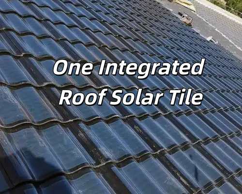
  • How GreenMore Ensures Professional Sample Customization for Solar Tile and Energy Storage Projects
    How GreenMore Ensures Professional Sample Customization for Solar Tile and Energy Storage Projects Aug 18, 2026
    L Luke Product Manager, GreenMore · Photovoltaic building materials GreenMore provides a structured and transparent sample customization policy for solar tiles and energy storage systems. Our policy is designed to help partners evaluate materials, performance, installation methods, and project feasibility with confidence. In building-integrated solar and energy storage projects, early-stage clarity is essential. A physical sample is often the first tangible step that allows architects, EPC companies, developers, and integrators to: Validate material quality and appearance Confirm installation compatibility Review technical specifications Communicate design concepts with clients Reduce uncertainty before construction GreenMore's sample customization policy ensures every partner receives consistent, reliable, and project-ready samples. Learn more about GreenMore GreenMore sample customization process Scope of Sample Customization GreenMore's sample customization covers two major product categories: Solar Tiles (Roof-Integrated PV Materials) Samples can be customized in: Power output Cell type — CIGS thin-film or BC Back Contact Color — dark grey, graphite black, brown, custom colors Shape — three-curve, flat, overlap Energy Storage Systems (ESS) Samples include: Structural components Enclosure materials Terminal and interface layout samples Control module exterior samples Battery module enclosure samples (non-cell) These samples help engineering teams evaluate installation methods, layout planning, and structural compatibility. Sample Quantity Policy GreenMore provides flexible sample quantities depending on project needs: Solar Tiles: typically 1–3 pieces per project ESS Samples: provided based on structural or engineering requirements Bulk samples: available upon request for large-scale projects or design reviews This quantity range ensures partners can evaluate materials without unnecessary cost or waste. Sample Pricing Policy Sample pricing is determined by product type and customization level: Solar Tile Samples Pricing depends on: Power rating Cell type (CIGS thin-film / BC) Color customization Shape (three-curve / flat / overlap) ESS Samples Pricing depends on: Structural complexity Material type Interface layout requirements Sample fee credit: For qualified projects, sample fees may be credited toward future orders. This policy supports long-term cooperation and reduces early-stage cost pressure. Shipping & Logistics Policy GreenMore provides global sample delivery with full logistics support: Worldwide shipping available Shipping cost calculated by destination, weight, and courier method Customers may choose GreenMore logistics or their own courier International shipments include full tracking Protective packaging ensures safe delivery This ensures samples arrive in perfect condition regardless of distance. Lead Time Policy GreenMore follows a predictable and transparent delivery timeline: Solar Tile Samples: 7–15 days ESS Structural Samples: 10–20 days Special customization: timeline confirmed based on project requirements Clear lead times help partners plan design reviews and engineering schedules. Quality & Testing Standards All samples — whether solar tiles or ESS components — are produced using the same standards as full-scale products: Structural reinforcement Weather-resistant coating Electrical performance testing Material durability checks Dimensional accuracy verification This ensures the sample accurately represents the final delivered product. Who Should Request GreenMore Samples Our sample customization policy is designed for: Architectural design firms Real estate developers EPC companies Roofing and façade installers Solar and ESS integrators Government and public building planners Distributors and project consultants Samples help teams make informed decisions at the earliest stage of project development. Request a Sample GreenMore is a photovoltaic tile manufacturer specializing in BIPV building-integrated solutions. Our core product line — three-curve solar tiles, photovoltaic bricks, and photovoltaic curtain walls — is produced in-house using CIGS thin-film and BC back-contact technologies. Solar power systems and energy storage systems are provided as supporting components for complete BIPV projects. Our sample customization policy is built to support partners with clarity, consistency, and reliable technical standards. Whether evaluating solar tiles for roof-integrated PV projects or energy storage systems for commercial and industrial applications, our structured approach ensures every sample reflects real-world performance and installation conditions. To request samples or discuss your project requirements, reach out through our contact page or email export@gmsolarkit.com. L Luke · Product Manager, GreenMore Luke leads GreenMore's solar tile and BIPV product planning. He works with EPC partners and distributors on sample customization, installation design, certification, and project delivery across Europe, the Middle East, Africa, and the Americas.
  • GreenMore’s Fast‑Install Solar Tile System
    GreenMore’s Fast‑Install Solar Tile System Sep 26, 2026
    L Luke Product Manager, GreenMore  ·  Solar tiles & BIPV systems Most BIPV roofing projects still run like conventional PV jobs: a crew of two or three, heavy glass modules, aluminum racking, and on-site DC wiring. The installation itself, not the product, is what keeps small rooftop jobs expensive and hard to schedule. GreenMore designed its solar tiles around a different assumption — that one qualified installer should be able to carry, fit and connect a single tile on their own. This post walks through the engineering behind that, how the work actually proceeds on a roof, and where it does and doesn't make sense. GreenMore solar tile installation diagram Why Traditional BIPV Installation Is Slow Heavy modules need two people Conventional PV modules typically run 30–40 kg. Lifting one up a pitched roof, holding it in place and fastening it is not realistic work for a single installer, especially at height. Racking adds a long list of steps Every rail has to be measured, aligned, leveled, treated for corrosion and fastened before a single module goes on. Panel by panel, that easily runs to 10–15 minutes each, and the timeline drifts with roof geometry. On-site DC wiring is skilled, risky work Stripping, crimping, stringing and landing cables into combiner boxes calls for a trained electrician and coordination with whoever is placing modules. High-voltage strings on a roof are a genuine safety exposure. The labor cost dominates small jobs On a residential roof, multi-person labor, a multi-day schedule and a box of accessories can outweigh the hardware. That is the real barrier to scaling BIPV on smaller buildings. GreenMore's System-Level Redesign 1. Ultra-light dual-glass tiles, 15–25 kg each GreenMore solar tiles pair a thin dual-glass front with a composite lightweight back shell. At roughly 15–25 kg per tile, one installer can lift, position and seat them without a second pair of hands, and high-altitude handling is noticeably safer. The format suits pitched roofs and complex surfaces where full-size modules are awkward. See GreenMore lightweight solar tile specs → 2. Interlocking structure — no racking, self-aligning Aluminum racking is removed entirely. Tiles overlap vertically and lock into each other with horizontal male-female joints, so the roof surface becomes one rigid layer. Only the first tile and the edge tiles need screws. The installed roof is rated for level-12 wind conditions and is tested under IEC 61215 and IEC 61730. More on the structural advantages of photovoltaic tiles → 3. IP68 plug-and-play electrical connections Wiring arrives pre-assembled with IP68 waterproof connectors and an anti-misplug key, so there is no on-site stripping or crimping. With the optional micro-inverter, DC is converted to AC at tile level, which removes long high-voltage strings from the roof altogether and lowers the exposure installers work around. 4. Generation and waterproofing in one layer Each tile carries molded drainage channels and sealing strips. Roofing, waterproofing, insulation and generation go down in a single pass, so there is no separate waterproof membrane to install or later to disturb. The Single-Installer Workflow Step 1 — Base prep and reference tile, about 10 minutes Clean the roof surface, check battens and purlins, set the first reference tile and run a basic continuity check. Step 2 — Interlocking, 2–3 minutes per tile Drop each tile onto the vertical lap, close the horizontal interlock and add fasteners only where the design calls for them. Alignment follows the previous tile rather than fresh measurements. Step 3 — Inspection and grid connection, about 15 minutes Confirm every lock is seated, check the fastening points, verify the plug connections and commission. On a standard roof, one installer can lay 50–80 m² in a day — output that traditionally takes a two or three-person crew. Three Tile Types, One Fitting Logic Overlapping tiles handle 5°–45° pitched roofs and follow familiar tiling logic. Flat-roof tiles are built for low-slope commercial roofs and fast coverage over large areas. Triple-curve Han tiles fit curved, Chinese-style and architect-driven roofs where appearance is part of the brief. All three install the same way. Browse the GreenMore solar tile range → What Faster Installation Changes For homeowners, smaller crews and a one or two-day schedule take labor out of the quote, and the finished roof looks like a roof rather than mounted equipment. For EPC contractors, one trained installer can carry work that used to need three, onboarding is faster, and smaller BIPV jobs become worth taking on instead of being passed over. For the industry, lower installed cost is what moves BIPV from flagship projects toward ordinary buildings. Explore GreenMore BIPV solutions → Quality and Certification GreenMore solar tiles are tested and certified against CE, IEC 61215 / IEC 61730, EN 14782 and EN 1090-1, with ISO 9001 and ISO 14001 manufacturing systems, a Class C fire rating and level-12 wind-uplift resistance. They carry a 25-year linear power-output warranty and have been installed across more than 20 countries. Industry references: IEA global solar reporting — https://www.iea.org IRENA renewable energy data — https://www.irena.org IEC international standards — https://www.iec.ch Wrapping Up A genuinely useful BIPV product is not just a building material that makes electricity — it is a system that makes clean energy practical to install. By cutting weight, removing racking and moving wiring onto pre-tested connectors, GreenMore solar tiles let one installer do work that used to take a small crew. That is a quieter change than a new cell efficiency record, but it is the kind that actually moves BIPV onto more roofs. Written by Luke — Product Manager, GreenMore Luke leads GreenMore's solar tile and BIPV product planning. He works with EPC partners and distributors on installation design, certification and project delivery across Europe, the Middle East, Africa and the Americas.
1 2 3 4 5 6
A total of6pages

Subscribe To Our Newsletter

Stay up to date with GreenMore. We share new BIPV solar tile releases, product and certification updates, and field notes from our projects — no fluff, just the things that matter to installers, distributors, and system integrators. If there's something you'd like to see covered, drop us a line — we read every reply.

Copyright @ 2026 GreenMore All Rights Reserved. Network Supported

Sitemap / Blog / Xml / Privacy Policy

leave a message

leave a message
If you are interested in our products and want to know more details,please leave a message here,we will reply you as soon as we can.
submit

Home

Products

WhatsApp

contact