
Welcome to GreenMore
Welcome to GreenMore

By Peter Lu, Product Engineer at GreenMore | September 20, 2026
An EPC wins a 500 kWh commercial storage project with an option to double next year. Two paths follow. Size the DC converter for day-two load and let most of it run lightly loaded for 12 months, or size it for day one and replace the unit later, which means a shutdown, re-engineering, and paying twice.
A modular DC power supply offers a third path. Commission one module, then add units into the same rack as load grows. The GreenMore GM-LDC30 and GM-LDC60 support multi-module parallel expansion with active load sharing and hot-swappable replacement through the Parallel Expansion Interface. This is Part 3 of our four-part series: why parallel systems scale, how they share current, and where they fail when poorly planned.
A monolithic converter is one fixed block of power, sized at the factory. It is simple to specify, and at a single capacity point it can be cost-effective. Its limits show up during growth and failure. Scaling beyond its rating means a new unit. A fault takes the full block offline, and service usually requires a shutdown.
| Day-one sizing | Fixed rating, all capacity paid upfront | One module commissioned, racks added later |
| Scaling | Replace or add a full standalone unit | Slide in more 30/60 kW modules |
| Response to one fault | Total output lost | Remaining modules carry the load |
| Maintenance | Scheduled shutdown often required | Hot-swap with the system online |
| Capex profile | All upfront | Staged, aligned with project phases |
Modular hardware carries a small per-kW premium because each module has its own control and housing. It returns that premium through staged investment and service access. For EPCs and integrators building cabinets in phases, that trade usually favors modules. New to the building blocks? Start with our DC power module selection guide.
Paralleling converters is not just bolting them to the same bus. When two regulated sources sit in parallel, even a millivolt difference in output setpoint or unequal cable resistance pushes current toward one unit. One module overloads and overheats while the others run light. Published analyses of parallel converters show that matching terminal voltages and wiring impedances is required for even split, and identical cable resistance is effectively impossible on site (arXiv, 2024).
Three control methods handle this in practice:
GreenMore parallel DC power modules use load-sharing control to balance output current across units. Balanced current means balanced thermal stress, because the hottest module ages fastest. The conversion topology behind this, and why ripple stays low, is in Part 2 of the series.
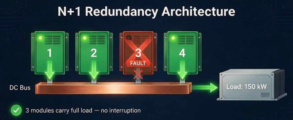 Schematic diagram of the N+1 redundancy working principle of the power supply system
N is the number of modules needed to carry the load, and +1 is a spare unit running in parallel. ENERGY STAR's UPS specification, built on IEC 62040-3 terminology, defines N+1 as a parallel system that tolerates one unit failing while staying in normal operation; IEC 62040-3 describes parallel and standby-redundant configurations in its annexes.
The numbers explain why. Following the method in the Vertiv/Liebert white paper Balancing Scalability and Reliability in the Critical Power System, a single unit's availability is:
A = MTBF / (MTBF + MTTR)
Illustrative values of 100,000 hours MTBF and 4 hours MTTR give A = 99.996% per unit, about 0.35 hours of expected downtime a year without redundancy. In an N+1 system the bus is available if all modules are up or exactly one is down, so for a 3+1 arrangement:
A(3+1) = R⁴ + 4R³(1 − R)
That yields roughly 0.3 seconds of expected downtime per year. The table compares the configurations using the same inputs.
| Architecture | Formula (R = single-unit availability) | Expected downtime per year |
| Single unit | R | ≈ 0.35 h |
| 1+1 | R² + 2R(1 − R) | ≈ 0.05 s |
| 3+1 | R⁴ + 4R³(1 − R) | ≈ 0.30 s |
Worked example: a 150 kW cabinet built with four 60 kW GM-LDC60 modules in 3+1. Normally each carries 37.5 kW. When one trips, the other three carry 50 kW each, within their rating, and output continues.
Two caveats keep this honest. The model assumes independent failures, but modules sharing one room, one cooling loop, or one firmware build can fail together. The same Liebert analysis also finds that beyond 3+1, added modules erode the benefit as complexity and service interventions rise; size modules so anticipated load is carried by at most three. That principle matches Uptime Institute's Tier III, where every capacity component can be removed for planned work without impact.
Picture a winter night: an alarm arrives that one DC module in an outdoor cabinet has faulted. With a monolithic supply, the sequence is a maintenance window, EMS coordination to keep the battery side stable, a service truck, and a shutdown before anyone touches hardware.
With hot-swappable parallel units, a technician slides out the failed module and inserts a spare while the others keep feeding the load. The RS485 link reports slot status and recognizes the replacement automatically. Firmware updates and fan service follow the same path. For integrators deploying air-cooled ESS cabinets, this is the difference between a daytime visit and a customer-notified outage.
Hot swap does not make every component redundant. The Liebert paper is explicit that a shared battery bank or a single system controller remains a single point of failure in a modular architecture. Module-level redundancy protects against module-level events.
Practical sizing follows the load in module steps:
Size the rack bus, AC distribution, and switchgear for the final configuration on day one even if slots stay empty. The same logic holds for liquid-cooled cabinets and containerized projects: modules are cheap to add later; switchgear is not.
Watch three traps. First, circulating current between modules with mismatched setpoints; verify setpoints before paralleling. Second, wiring asymmetry, where one module sees lower bus impedance and takes more current; use equal cable lengths and a symmetrical bus. Third, shared single points: one controller, one communications cable, or one fan group. Module redundancy is not system fault tolerance.
When a module fails, the OVP, OCP, SCP, and OTP chain that isolates it is detailed in Part 4 of the series.
Parallel expansion turns the DC power system from a fixed purchase into a capacity plan: single-module commissioning today, multi-unit racks next year, with load sharing and N+1 protection built in. GreenMore has worked in solar and energy storage since 2017, and our engineers bring more than 10 years of power-electronics experience to cabinet and container designs. The GM-LDC30 and GM-LDC60 carry a 3-year warranty and are ready for parallel configurations.
Planning a scalable DC system for an upcoming cabinet project? Contact the GreenMore team with your load profile and expansion timeline, and we'll size the string.
Please Read On, Stay Posted, Subscribe, And We Welcome You To Tell Us What You Think. BIPV solar tiles & energy storage — updates for global partners.




Copyright @ 2026 GreenMore All Rights Reserved.  Network Supported
Sitemap / Blog / Xml / Privacy Policy


