OVP, OCP, SCP, OTP: A Practical Guide to DC Power Protection
Sep 21, 2026
By Peter Lu, Product Engineer at GreenMore | September 20, 2026
A DC power module sitting in an energy storage cabinet has to survive events no operator plans for. A maintenance crew lands the battery leads on the wrong terminals. A summer thunderstorm couples a surge onto the DC bus. A fan bearing seizes and the heatsink starts to climb. At a remote telecom site, the feeder voltage sags every evening when the village load peaks.
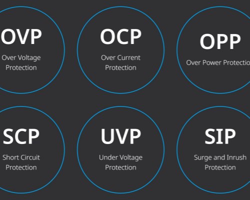
This is the fourth post in our series on GreenMore DC power modules. It explains what OVP OCP SCP OTP actually guard against, why reverse polarity, surge and insulation monitoring belong on the same feature list, and how a wide input voltage range keeps a site running through grid and battery swings. It also gives you a checklist for verifying protection before you specify a module.
Why Do DC Power Modules Need Four Separate Protections?
Each protection answers a different failure mode, and none is a substitute for another. The thinking behind this layered approach matches how modern product safety standards are written. IEC 62368-1 is a hazard-based standard. It asks designers to identify electrical, thermal and fire energy sources and put safeguards between them and people or equipment. The standard replaced the older IEC 60065 and IEC 60950-1 and moved toward performance-based requirements, as TÜV Rheinland summarizes in its overview of the IEC 62368-1 transition. Its component annex covers overcurrent protective devices and thermal cut-offs, and it requires a protective device to have enough breaking capacity to interrupt the maximum fault current.
Translated to the field, that framework maps to four common faults:
OVP
Output or bus overvoltage
Regulator failure, load dump, battery disconnection under load
Sensitive loads and DC-side capacitors see a voltage above rating and can fail instantly
Clamp or shut down the output; restart only after voltage returns to range
OCP
Sustained overcurrent
Overload, stalled load, partial wiring fault
Semiconductors and cables overheat; accelerated wear or fire risk
Current limit, then reduce or cut output if the overload persists
SCP
Hard short circuit
Tool dropped across bus bars, insulation failure, shorted cable
Near-instant destructive current; arcing and fire at the fault point
Fast current cutoff; restart attempts timed to limit energy
OTP
Overtemperature
Fan blocked, high ambient, clogged filter, prolonged overload
Thermal runaway, component derating, shortened service life
Throttle or shut down; auto-resume after cooling
Response behavior generally falls into two families. In hiccup mode, the converter shuts off, waits, and attempts a soft restart, repeating the cycle until the fault clears. Texas Instruments notes that hiccup gives a system "a chance to recover without external intervention" while cutting power and heat during a short; see their article on hiccup and latch-off fault responses. The alternative is latch-off, which holds the converter off until the enable pin or supply is cycled, a safer choice when a central controller must decide what happens next. Exact thresholds and restart behavior vary by design, so confirm them in the product manual before commissioning.
What Are Reverse Polarity, Surge Protection and Insulation Monitoring?
Beyond the four lettered protections, the GreenMore module spec lists three more items worth understanding.
Reverse polarity protection blocks current when the positive and negative conductors are swapped. Battery banks are the usual culprit: during commissioning or a pack replacement, a single reversed connection can drive current through electrolytic capacitors and semiconductors within seconds. A series diode or, more efficiently, a MOSFET-based power path keeps the reverse voltage from reaching the module's electronics.
Surge protection deals with short, high-energy transients rather than steady overvoltage. IEC 61000-4-5 is the reference standard for surge immunity testing, covering unidirectional surges generated by switching and lightning transients and defining test levels for different installation environments. Cabinet-level surge protective devices handle the bulk of a lightning or switching event, and built-in module protection covers whatever residual transient reaches the DC input.
Insulation monitoring applies to unearthed DC systems. When live conductors have no solid connection to earth, a first insulation fault causes no immediate short and no breaker trips, so it can sit undetected until a second fault on the other pole creates a phase-to-phase short. An insulation monitoring device, or IMD, continuously measures the resistance between the live conductors and earth and raises an alarm as it falls. IEC 61557-8 specifies requirements for these devices for unearthed DC IT systems up to 1500 V, including detection of the symmetrical insulation deterioration common on the DC side. It is an early-warning function, not a shutdown by itself.
Schematic diagram of GreenMore energy storage system security protection mechanism
Why Does a Wide Input Voltage Range Matter on Weak Grids?
A module that only accepts a narrow voltage band will nuisance-trip in environments that are already normal for many site operators. Three scenarios come up repeatedly.
First, weak and remote grids. On long feeders with high line impedance, voltage drops under evening peak load. Add a diesel generator at the end of a weak line and it gets worse: genset voltage steps and dips as large loads switch in, and may drift for seconds at a time. Every bus transfer pushes the DC link around.
Second, battery voltage is not constant. A battery string starts low under heavy discharge, recovers during charging, and shifts with state of charge, temperature and age. The converter has to follow the full swing rather than dropping out mid-discharge.
Third, telecom power practice already assumes this spread. ETSI EN 300 132-2 defines the normal service voltage range for a nominal -48 V supply as -40.5 V to -57.0 V, a tolerance of roughly -15.6% to +18.8% around nominal. Equipment built for a narrow band can trip inside a perfectly healthy telecom room.
The GreenMore GM-LDC30 and GM-LDC60 DC power modules are designed as a wide voltage DC power module platform. The low-voltage side operates from 200 to 900 V, with 900 V maximum, and the high-voltage side operates from 300 to 1000 V, with 1000 V maximum. That window covers battery charge and discharge swings, generator stepping and weak-feeder sags without forcing a shutdown.
Zero-Intervention Reliability for Unattended Sites
Protection is only half the story at a site nobody visits weekly. A module that trips and then waits for a manual reset leaves an ESS or UPS offline until the next scheduled visit, which could be weeks away at a remote telecom shelter.
Zero-intervention reliability means the module handles faults inside its operating envelope and returns to service on its own when conditions normalize. Hiccup-style restart after a transient short, automatic resume after a temperature event, and continued regulation across a wide input range all serve the same goal: keep the cabinet available without a truck roll. The standby draw stays below 20 W, so idle protection and monitoring do not erode site efficiency.
The same logic applies across the cabinet range. GreenMore applies the principle to its air-cooled energy storage cabinets, and it carries over to liquid-cooled and containerized deployments where site visits are even more expensive. The modules run from -30 °C to +55 °C, at altitudes up to 3000 m, with smart air cooling that only spins fans as needed, reducing one of the common causes of OTP events.
How Do You Verify Protection When Selecting a DC Module?
Ask for specifics instead of accepting an acronym list. Work through these points:
Confirm every protection is named in the datasheet, not just implied. OVP, OCP, SCP and OTP should each appear, along with reverse polarity, surge and insulation monitoring.
Request the actual trip thresholds and tolerances. An OVP set point sitting too close to normal bus voltage causes nuisance trips; one too high leaves little margin.
Ask whether each fault latches off or auto-recovers, and whether the behavior can be configured over the RS485 interface. Match that choice to who responds to alarms at the site.
Check that the input range covers the real battery and grid envelope, including end-of-discharge voltage and generator conditions, not just nominal.
Verify the operating temperature and altitude ratings against the installation location, and confirm cooling type and airflow clearance.
Confirm insulation monitoring reports through the system controller so a first earth fault triggers a visible alarm rather than a silent log entry.
The other posts cover DC module fundamentals and cabinet fit, how the conversion stage reaches 98.0%–98.6% efficiency with low ripple, and how rack modules scale through parallel expansion.
GreenMore has worked in solar and power electronics since 2017, and the GM-LDC30 and GM-LDC60 carry a three-year warranty. If you are sizing a DC module with intelligent protection for an ESS, UPS, telecom or industrial control site and want help matching protection and voltage range to your conditions, talk to our team.






 Network Supported

