
Welcome to GreenMore
Welcome to GreenMore
Every battery storage project has one device that everything else is negotiated around. The battery sets the voltage window, the grid sets the code, and the power conversion system has to satisfy both. Get it wrong and the battery either charges slower than the site needs or the inverter trips on a voltage the cells reach every day in winter.
A PCS is not an inverter with a bigger cabinet. It is a bidirectional converter that runs the battery against a grid, and the difference shows up in the specifications that decide whether a project works.
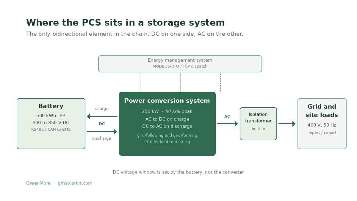
The PCS is the only bidirectional element in the chain. Everything upstream of it stores DC; everything downstream runs on AC.
On the DC side sits the battery, a stack of modules with a voltage that swings from full charge down to cutoff. On the AC side sits a transformer, then the grid or the site's distribution board. The PCS is the single piece of equipment that faces both, and it has to hold its output steady while the input voltage moves by hundreds of volts.
That is where it differs from the three devices it gets confused with. A grid-tied solar inverter is unidirectional and optimizes for maximum power point tracking. A variable frequency drive runs a motor at varying speed. A phase converter changes single-phase into three-phase. None of them charges a battery, and none of them has to reverse power flow on command.
The core function is a bidirectional bridge. Charging, it rectifies grid AC into DC at whatever voltage the battery currently presents. Discharging, it inverts DC back to AC and holds voltage and frequency while the load changes. Both directions pass through the same silicon, which is why a PCS is rated for apparent power in both modes rather than for one.
A grid code rarely asks only for watts. Modern PCS units control active and reactive power independently, with a power factor adjustable from 0.99 leading to 0.99 lagging. At full rated power the current total harmonic distortion stays under 3%, which is what allows a unit to connect to a weak distribution network without a filter bank.
Off grid there is nothing to follow, so the PCS becomes the reference. It sets 400 V and 50 or 60 Hz for the whole site, and every load hangs off that. On our units this is a selectable mode rather than a separate product, with optional seamless transfer and diesel generator integration for weak-grid sites.
Ten lines decide whether two PCS units are actually comparable. Anything outside these is usually a variant of the same number.
| Parameter | Why it decides the project |
|---|---|
| DC voltage window | Must span the battery from full charge to cutoff, not just the nominal voltage. A 500 to 850 V unit cannot serve a 1000 V rack. |
| Rated power, kW | Sets charge and discharge rate. C&I units run 50 to 630 kW, utility units 1.25 to 1.725 MW. |
| Maximum output, kVA | The figure that matters at a power factor below 1. Often 10% above the kW rating. |
| Maximum DC current, A | The real limit at low state of charge. Power divided by minimum voltage gives the current, and this is where sizing fails. |
| Efficiency | A peak figure, measured at optimum load. Ask for the curve, not the peak. |
| Overload capability | Motor starts and load steps need headroom. 110% continuous is common on transformer units. |
| Unbalanced load | 100% three-phase imbalance support matters on C&I sites where single-phase loads dominate one leg. |
| Topology | A built-in isolation transformer gives galvanic isolation and survives harsh sites. Transformerless high-frequency designs are lighter and slightly more efficient. |
| Protection rating and temperature | IP20 for an indoor equipment room, IP54 for an outdoor cabinet. Below minus 20 or above plus 50, derating starts. |
| Altitude | Above 2000 m, air cooling loses effectiveness and the unit must be derated or the site needs forced ventilation. |
We build two ranges, and the split is not arbitrary. It follows the battery voltage. Indoor commercial systems run 500 to 850 V DC and need galvanic isolation. Utility-scale containers run 800 to 1500 V DC, where a transformer at that power level would cost more than it protects.
| GM-LEG50KT to 630KT | GM-LEG1250K to 1725K | |
|---|---|---|
| Rated power | 50, 100, 250, 500, 630 kW | 1250, 1575, 1725 kW |
| Maximum output | 55 to 693 kVA | 1512 to 1897 kVA |
| DC voltage window | 500 to 850 V | 800 to 1500 V, or 915 / 1000 V minimum |
| Maximum DC current | 79 to 1000 A | 1935 A |
| Peak efficiency | 97.6% | 98.0% |
| Isolation transformer | Built in | None |
| Protection | IP20, indoor equipment room | IP54, outdoor cabinet |
| Operating temperature | Indoor, ventilated room | minus 30 to plus 60 degrees |
| Grid voltage | 3W/N/PE, 400 V | 550, 630 or 690 V |
| Cooling | Forced air | Intelligent forced air |
The transformer line costs about half a point of efficiency and gains a floating DC bus, which is what keeps a fault in one battery rack from reaching the AC side. On a 250 kW commercial system that half point is roughly 1,200 kWh a year at 1,000 full-load hours. On a site where the battery sits in a shed next to a workshop, most buyers take the isolation.
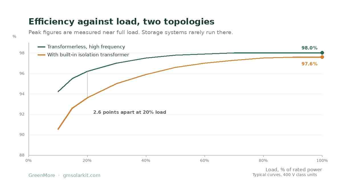
Peak efficiency is measured near full load. Most storage systems spend their life well below it.
A datasheet quotes one number, taken near rated power at nominal voltage and 25 degrees. Real systems run at part load most of the day, and the curve falls away from the peak faster on transformer units because the transformer's no-load loss is fixed.
Two consequences follow. First, a PCS sized at exactly the battery's maximum discharge rate will spend its life at 20 to 40% load, where a transformer unit may sit several points below its rating. Second, the loss is not only the converter's: at part load the transformer's magnetising current becomes a larger share of throughput, so oversizing for headroom has a running cost as well as a capital one.
The practical rule is to size at the battery's continuous rate, not its peak, and to check the curve at 25% load rather than at 100%.
Take a 500 kWh lithium iron phosphate battery with a 600 to 850 V window, and a site that needs 250 kW for two hours at the evening peak. The battery is asked for 0.5C, which is comfortable.
At 800 V nominal, 250 kW draws 312 A. At the bottom of the window, 600 V, the same 250 kW needs 417 A. A 250 kW unit rated at 397 A maximum DC current therefore delivers only 238 kW at 600 V. The unit is not faulty; it is being asked for more current than its bridge is rated for.
Three ways out: raise the battery's minimum voltage by changing the module count, accept 238 kW at the bottom of the window, or move up a frame. Most projects take the first option, because it costs nothing at the design stage and everything after commissioning.
| Check | Figure | Result |
|---|---|---|
| Battery energy | 500 kWh, 600 to 850 V | 0.5C at 250 kW |
| Current at nominal | 250 kW at 800 V | 312 A |
| Current at cutoff | 250 kW at 600 V | 417 A |
| Unit rating | GM-LEG250KT, 397 A max | 238 kW available at 600 V |
| Fix | Raise minimum to 630 V | 250 kW within 397 A |
| DC cable loss | 70 mm2, 50 m one way, 312 A | 2.6 kW, about 1% of throughput |
DC cable between battery and PCS carries the full current at low voltage, and the loss scales with the square of it. A 70 mm2 copper run of 50 m carries 312 A with about 0.027 ohm of loop resistance, which is 2.6 kW of heat at full load. Over 3,000 equivalent full-load hours that is 7,850 kWh a year, more than the difference between a 97.6 and a 98.0% converter.
This is the most common silent loss in a containerised system: the PCS is specified carefully and the cable is whatever fits the gland plate.
A PCS connects a DC source to an AC network, so it inherits both equipment safety and grid interconnection duties. These are the documents a European or Middle Eastern utility will ask for.
| Standard | Scope | Where it applies |
|---|---|---|
| IEC 62477-1 | Safety of power electronic converter systems | The base safety standard for the PCS itself |
| IEC 62933-2-1 | Storage system parameters and test methods | Defines how rated power and efficiency are measured |
| IEEE 1547 | Interconnection of distributed energy resources | North America, and widely referenced elsewhere |
| UL 1741 SB | Certification to IEEE 1547-2018 | Required for grid connection in the US |
| EN 50549-1 and -2 | Connection of generating plants | Referenced across EU member states |
| VDE-AR-N 4110 | Connection to the German medium-voltage grid | Required for German C&I projects |
| IEC 61000-3-12 | Harmonic current limits | Low-voltage connection, above 16 A per phase |
Ask for the certificate number and the issuing body, not a logo. A PCS certified to IEC 62477-1 alone is a safe device but not a grid-compliant one, and the difference only surfaces when the utility rejects the commissioning report.
Four failures account for most of the commissioning problems we are called in to fix.
The first is a voltage window that fits on paper and not in winter. A battery at 5 degrees sits lower than the datasheet curve suggests, and the PCS hits its minimum input voltage before the cells reach their own cutoff, so usable capacity is quietly 8% below nameplate.
The second is overload. A site with three 90 kW motors starting in sequence will trip a converter sized for steady state. The transformer units carry 110% continuously for exactly this reason, and even then the start sequence matters.
The third is heat. A unit rated for 50 degrees in a container in the Gulf is rated for less inside that container, because the cabinet's internal ambient runs above the outside air. Derating is not optional there.
The fourth is the isolation decision made late. If the site turns out to need galvanic isolation after the transformerless unit is ordered, the fix is an external transformer and a new footprint.
We build both PCS ranges: the GM-LEG KT series from 50 to 630 kW with a built-in isolation transformer, and the GM-LEG MW series from 1.25 to 1.725 MW per unit for outdoor containers. Both support grid-tied and off-grid operation, 100% unbalanced load, and MODBUS-RTU or TCP dispatch.
Send the battery voltage window, the required power and whether the site is grid-tied, off-grid or a hybrid microgrid, and we will size the converter against the current limit rather than the nameplate. Every unit carries a 3-year warranty.
No. A phase converter turns a single-phase supply into three-phase power for a motor. A PCS is a bidirectional AC to DC converter that charges and discharges a battery and provides grid-support functions.
They overlap but are specified differently. A storage inverter is usually a wall-mounted unit for a building, with a fixed battery voltage range. A PCS is built for containerised systems, with a wider DC window, higher current ratings and utility-scale grid functions.
Not always. A built-in transformer gives galvanic isolation and tolerance of harsh sites, at about half a point of efficiency. Transformerless high-frequency designs are lighter and slightly more efficient, and suit containers where the battery has its own protection.
Yes, as a selectable mode. The unit forms its own voltage and frequency reference, and on our ranges supports optional seamless transfer and diesel generator integration for microgrids.
By paralleling units. Two 1.725 MW converters give 3.45 MW, and capacity can be added in stages so a single unit can be serviced without shutting the plant down.
Between 96 and 97% average round-trip on a transformer unit, and 97 to 98% on a transformerless one, once part-load operation and cable loss are included. Peak datasheet figures are reached near rated power only.
Energy Storage Product Manager, GreenMore
Works on commercial, industrial and utility storage projects, mostly on the interface between battery voltage windows, converter ratings and grid codes.
Updated on November 17, 2026
Stay up to date with GreenMore. We share new BIPV solar tile releases, product and certification updates, and field notes from our projects — no fluff, just the things that matter to installers, distributors, and system integrators. If there's something you'd like to see covered, drop us a line — we read every reply.




Copyright @ 2026 GreenMore All Rights Reserved.  Network Supported
Sitemap / Blog / Xml / Privacy Policy


