What is a Power Conversion System (PCS)?
May 05, 2025
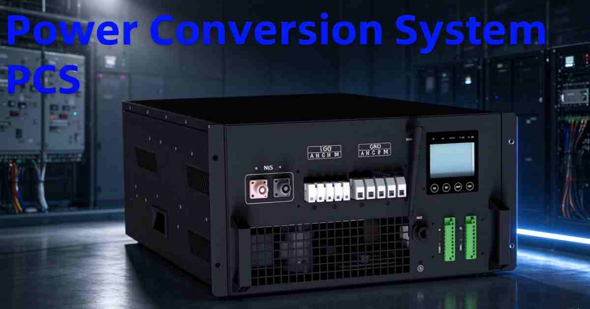
A power conversion system is the bidirectional converter between a battery and the grid or the loads. The battery stores DC. The grid and almost every load run on AC. The PCS is the only device in the chain that faces both. Charging, it turns AC into DC. Discharging, it turns DC back into AC and holds the output steady while the battery voltage falls through its whole working range.
It is not an inverter with a larger cabinet. A solar inverter takes DC from an array at whatever voltage the sun happens to give it and pushes AC out. A PCS holds its AC side fixed while its DC side swings with state of charge, and it reverses direction on command. That single difference drives most of the specification, and it is where quotes from different vendors stop being comparable.
How a PCS works
The power stage is a bridge of IGBTs, or increasingly SiC MOSFETs, switching somewhere between 2 and 20 kHz. High-voltage IGBTs above 3 kV sit at the bottom of that range, around 2 to 3 kHz, because switching loss climbs with the voltage being commutated. A controller generates the pulse pattern, and an LCL filter on the AC side removes the switching harmonics, so the current that reaches the transformer meets the power quality limits in the local grid code.
There is no separate charger. The same silicon runs in both directions:
Charging. Grid AC is rectified to DC at whatever voltage the battery currently presents, following a current profile the BMS has approved.
Discharging. Battery DC is inverted to AC matching grid voltage, frequency and phase, and the output holds while the site load moves.
The controller sits between two authorities. The BMS owns the limits: permitted charge and discharge current, voltage window, cell temperature, fault states. The EMS owns the schedule: when to charge, when to discharge, how much. The converter executes inside both. When a unit trips on a voltage the cells reach every winter, the fault is usually in the boundary between those two rather than in the bridge.
Grid-tied storage layout: PV array, on-grid inverter, battery pack, grid and load.
Core functions
A storage PCS does more than move watts. It is the actuator for whatever the site or the grid operator asks the system to do, and each of those functions has a number attached to it that a datasheet either states or avoids.
Function
What it means in practice
Bidirectional power flow
Charge and discharge through one unit, with ramp rates inside what the grid code allows
Active and reactive power, controlled separately
Power factor adjustable from 0.8 leading to 0.8 lagging, which is what a weak distribution network asks for
Grid-connected and off-grid operation
Grid-following when connected; grid-forming to establish 400 V at 50 or 60 Hz when the grid is not there
Fast response
Output moves within milliseconds, which is why storage gets dispatched for frequency regulation rather than for baseload
Protection and anti-islanding
Over and under voltage, over and under frequency, overcurrent, DC reverse polarity, islanding detection
Overload headroom
110% of rated power continuously, because motor starts and load steps do not wait for a schedule
The last row is the one buyers skip. A converter sized exactly at steady-state load has nothing left for a chiller starting, and the trip gets logged as a grid fault rather than as a specification error. The other numbers a utility reads before it accepts the unit are THDi below 3% on grid, and THDu within 1% for linear loads and 5% for non-linear ones off grid.
PCS vs a solar inverter
The boxes look alike. Both are three-phase AC units with a DC input. Both carry grid-code certificates, and often both are sold by the same company. The operating logic is not the same.
Attribute
Solar (PV) inverter
Storage PCS
Power direction
One way, array to grid
Both ways, grid to battery and back
What sets the DC voltage
Maximum power point tracking, often 200 to 850 V on a 1,000 V string unit
The battery's state of charge, 672 to 850 V on a 768 V rack
Control authority
Irradiance and the MPPT algorithm
BMS limits and EMS dispatch
Reactive power
Usually unity, or a narrow adjustable band
Four quadrant, 0.8 leading to 0.8 lagging
Off-grid operation
None without a battery and a second inverter
Forms its own voltage and frequency reference
Overload
Sized for continuous irradiance
110% continuous, more for short motor starts
Certification
IEC 62109 product safety plus the local grid code
IEC 62477-1 safety plus the grid code, with grid-forming tested separately
The second row is where most projects get into trouble. A string inverter's DC window is a tracking range: the array can sit anywhere inside it and the inverter finds the power point. A PCS's DC window is a hard limit, and the current it needs at the bottom of that window is higher than at the top, because power is volts times amps. Size from the minimum voltage rather than the nominal one, or the unit will be current-limited exactly when the site needs it most.
Hybrid inverters collapse both roles into a single residential box, with MPPT inputs for panels and a battery terminal on the same DC bus. Above roughly 30 kW the two functions separate again, because a commercial PCS is sized in tens or hundreds of kilowatts and its DC side is built around a battery rack rather than around a string of modules.
Topology: two-level vs three-level
The internal switching arrangement decides harmonics, losses and filter size. It is also the one line on a PCS datasheet that buyers almost never ask about, which is why two units quoting the same peak efficiency can behave differently at the load the site actually runs at.
A two-level bridge switches the full DC bus across the output. Each phase leg connects the output to either the positive or the negative rail, so the voltage waveform is a train of pulses jumping between plus and minus the bus voltage. It uses few devices and simple control, and it is the standard choice below a few hundred kilowatts.
A three-level neutral-point-clamped bridge adds a midpoint connection and clamps every switching device to half the bus. The output can now sit at the positive rail, the midpoint or the negative rail, so a single switching event moves half the voltage it did before. The waveform is closer to a sine before any filtering happens, which is what the rest of the benefits follow from.
Switching loss scales with the voltage being commutated, so halving the commutation voltage roughly halves the loss per event. Harmonic content falls for the same reason, which lets the LCL filter shrink and the audible noise drop with it. The efficiency gain is usually half a point to a full point at part load, and part load is where a storage converter spends most of its life.
The price is device count and control. A three-level leg needs four switches and two clamping diodes where a two-level leg needs two switches, plus a modulator that keeps the midpoint voltage balanced under uneven loading. That extra hardware and extra firmware are the reason three-level designs appear above roughly 250 kW and rarely below it.
Attribute
Two-level
Three-level NPC
Devices per phase leg
2 switches
4 switches and 2 clamping diodes
Voltage across each device
Full DC bus
Half the DC bus
Switching loss per event
Baseline
Roughly half
Waveform before filtering
Pulses between plus and minus bus
Three levels, closer to a sine
Filter
Baseline LCL
Smaller LCL, lower ripple
Control
Simple PWM
Midpoint balance, more complex modulation
Typical power range
Up to about 250 kW
250 kW and above
Below a few hundred kilowatts the extra devices cost more than the half point of efficiency and the smaller filter they buy back. Above that, the LCL filter a two-level unit needs to hit the same ripple current at 1,500 V DC is physically larger than the silicon it saves, and the arithmetic goes the other way.
Typical applications
The application decides which of the specifications above actually matter, and two of them carry most of the weight: overload and response time.
Application
What the PCS does
What sets the rating
Peak shaving and arbitrage
Charges on a low tariff, discharges into the evening peak
Discharge duration and the site load profile
Demand charge management
Trims the monthly peak in 15 to 30 minute blocks
Power rating rather than energy
PV smoothing and ramp control
Absorbs and releases to hold export inside a ramp limit
Response speed and round-trip efficiency
Microgrid and weak grid
Forms voltage and frequency for the island
Grid-forming capability and overload margin
Frequency regulation
Follows a dispatch signal within seconds
Response time and communication latency
Backup
Carries critical loads through an outage
Transfer time and the surge from motor loads
Microgrid application scenarios: local distribution, telecom base stations, factories, farms, hospitals and hotels.
Demand management and backup are where undersized units show up first. The first needs full power for a quarter of an hour at a time, so a converter with no overload margin clips the peak it was bought to clip, and that peak is usually set by the highest interval in the month rather than by the average day (EIA publishes the tariff data behind those peaks). The second has to ride through a motor start, which is a surge the steady-state rating does not describe. Both are then paid for through round-trip efficiency, which sets the running cost: 94 to 97% on a transformer unit, a point higher without one, measured across a full charge and discharge rather than at a single operating point, which is the same basis the IEA uses when it weighs storage against other flexibility options.
How to select a PCS
Six checks cover most of the mistakes that turn up at commissioning.
Rate for continuous power, then add the overload. Motor starting and load steps need headroom above the steady-state figure, and 110% for a few seconds is not the same as 110% continuously. Ask which one the datasheet means.
Size from the bottom of the DC voltage window. Current rises as voltage falls, and the bridge has a current limit that does not move with the battery. A unit that delivers its nameplate figure at nominal voltage may deliver noticeably less at the low end.
Read the efficiency curve at 25% load. Storage spends most of its life at part load, and that is where two units quoting the same peak number separate. A transformer adds a fixed no-load loss that matters more the further the unit sits from rated power.
Get the unbalanced load capability as a number. Three-phase sites with single-phase loads need a stated percentage, not a claim of full support, and the answer decides whether the converter can run a mixed board.
Check the certificate number and the issuing body. IEC 62477-1 is equipment safety and says nothing about grid connection. EN 50549-1 covers low-voltage connection, EN 50549-2 medium voltage, and EN 50549-10 is the test method introduced in 2022 that European utilities began asking for in 2023, with grid-forming assessed separately again. A certificate is not the same as permission to connect either, and the interconnection process behind it differs by region, which is the part the DOE storage programme documents.
Match the protocols before the order. Modbus RTU or TCP and CAN are the common interfaces. A converter that cannot talk to the site's EMS cannot be dispatched, and the site will end up running it by hand.
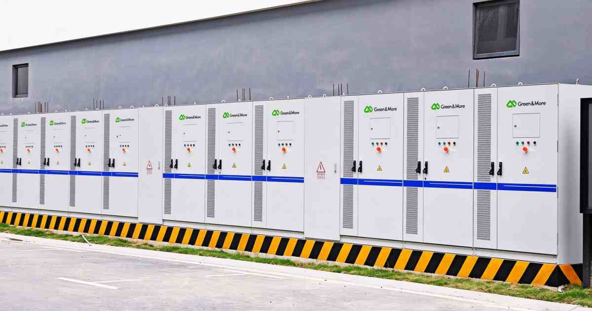
Most units ship inside a cabinet or a container rather than as a standalone box, so the converter specification usually arrives as part of a system datasheet. The 5 MWh container lists AC and DC data for a 500 kW and a 1,000 kW unit side by side, which shows how far the two ratings diverge on the same platform. The commercial storage category covers the cabinet range from 30 to 100 kW. If the question is which enclosure the converter ends up in, outdoor cabinets and containers are the two answers, and for the sizing arithmetic worked line by line, the engineering walk-through takes a 500 kWh example from the battery window to the cable loss. To match a converter against a battery and a site, use the contact page.
Frequently Asked Questions
Can I use an ordinary solar inverter instead of a PCS for storage?
Not for a DC battery. A standard PV inverter converts DC from panels into AC and cannot charge a battery or follow a BMS command, because its power stage is unidirectional and its control loop is built around maximum power point tracking. A hybrid inverter is the residential exception, carrying MPPT inputs and a battery terminal in the same box. Commercial storage uses a dedicated bidirectional converter, and the two are specified from opposite ends: the inverter from the array, the PCS from the battery.
What is the difference between grid-following and grid-forming?
A grid-following converter synchronizes to an existing grid and injects a set amount of power. It cannot run alone, because there is nothing to lock onto. A grid-forming converter establishes its own voltage and frequency reference, so the system can run off grid or start a dead microgrid after a blackout. The capability has to be specified in both the hardware and the controls, and under EN 50549-10 it is tested as a separate function rather than assumed from the presence of an off-grid mode.
How is PCS size chosen for a storage project?
From the required power and the duration, which together define the C-rate. A 100 kWh battery asked to deliver 50 kW for two hours needs at least a 50 kW converter with overload margin. The same battery asked for 100 kW for one hour needs 100 kW. After that, check the current at the bottom of the battery's voltage window, because that is the point where the nameplate figure stops being true, and it is the check most often skipped when a converter is bought from a catalogue.
Why does a PCS need to communicate with the BMS?
The BMS is the authority on what the cells can take. It reports permitted charge and discharge current, the voltage window and any fault states, and the converter has to stay inside all of them. The EMS sets the schedule and the BMS sets the boundary; a converter that ignores either will either underuse the battery or damage it. This is also why the protocol matters: a converter that reads only a start and stop signal cannot follow a charge profile, and will either trip on a BMS limit or sit idle.
Two-level or three-level, which should I specify?
Below roughly 250 kW, two-level. The extra devices, the midpoint control and the larger firmware surface cost more than the half point of efficiency and the smaller filter they buy. Above that, three-level, because at those currents the filter a two-level unit needs to meet the same ripple limit at 1,500 V DC is bigger than the silicon it saves, and the switching loss stops being a rounding error. The power range on the datasheet is usually a good guide to which one the vendor actually builds.
Which parts of a PCS fail first?
The electrolytic capacitors, typically at 5 to 10 years. The cooling fans or pumps, at 5 to 7 years. The IGBT modules, at 10 to 15 years under normal loading. The bridge is rarely the first thing to go, which is why the maintenance line items on a storage site are cooling and DC-link capacitance rather than power semiconductors. It also explains why a converter in a hot cabinet reaches those limits earlier than the datasheet suggests, since capacitor life roughly halves for every 10 degrees of sustained ambient.
P
Peter Lu
Energy Storage Product Manager
Works on the converter side of storage projects, mostly on DC voltage windows, current limits at the bottom of the battery range, grid-forming capability and the certification path from IEC 62477-1 to a national grid code.
Updated on November 18, 2026






 Network Supported


